
CNC Double Knife Turning Vertical Lathe

A turning and vertical turning technology, applied in turning equipment, turning equipment, wheels, etc., can solve the problems of multiple operators, occupy a lot of space, affect the turning accuracy of wheels, etc. The effect of machining accuracy

Active Publication Date: 2018-03-06
泉州市泰智机械发展有限公司
View PDF9 Cites 0 Cited by
  • Summary
  • Abstract
  • Description
  • Claims
  • Application Information

AI Technical Summary

Problems solved by technology

[0003] For example, on a car wheel, there are many places on the circumferential surface that need to be turned, such as the outer bottom surface of the wheel, the inner and outer chamfers of the center hole, the outer circle of the lock groove, the lock groove, the outer circular surface of the rim, the lower end surface of the rim, and the inner and outer chamfers. Turning, etc., using the existing turning method, the turning of a wheel needs to go through multiple processing procedures and multiple turning machines, and after each processing is completed, it must be disassembled and transported to the next process of turning. Mechanically, the workpiece is fixed and installed again. The wheel is an industrial workpiece that needs to be processed finely. However, in the current turning processing method, the wheel needs to be fixed and installed on different machines, so that the wheel cannot have a fixed position relative to each process. This will affect the turning accuracy of the wheel, and it will take a long time to complete turning a wheel, requiring more operators, and the labor intensity of manual handling is relatively high. In addition, multiple machines in multiple processes need to take up a lot of space

Method used


Image

  • CNC Double Knife Turning Vertical Lathe
  • CNC Double Knife Turning Vertical Lathe
  • CNC Double Knife Turning Vertical Lathe

Examples


Embodiment Construction

[0065] In order to further explain the technical solution of the present invention, the present invention will be described in detail below through specific embodiments.

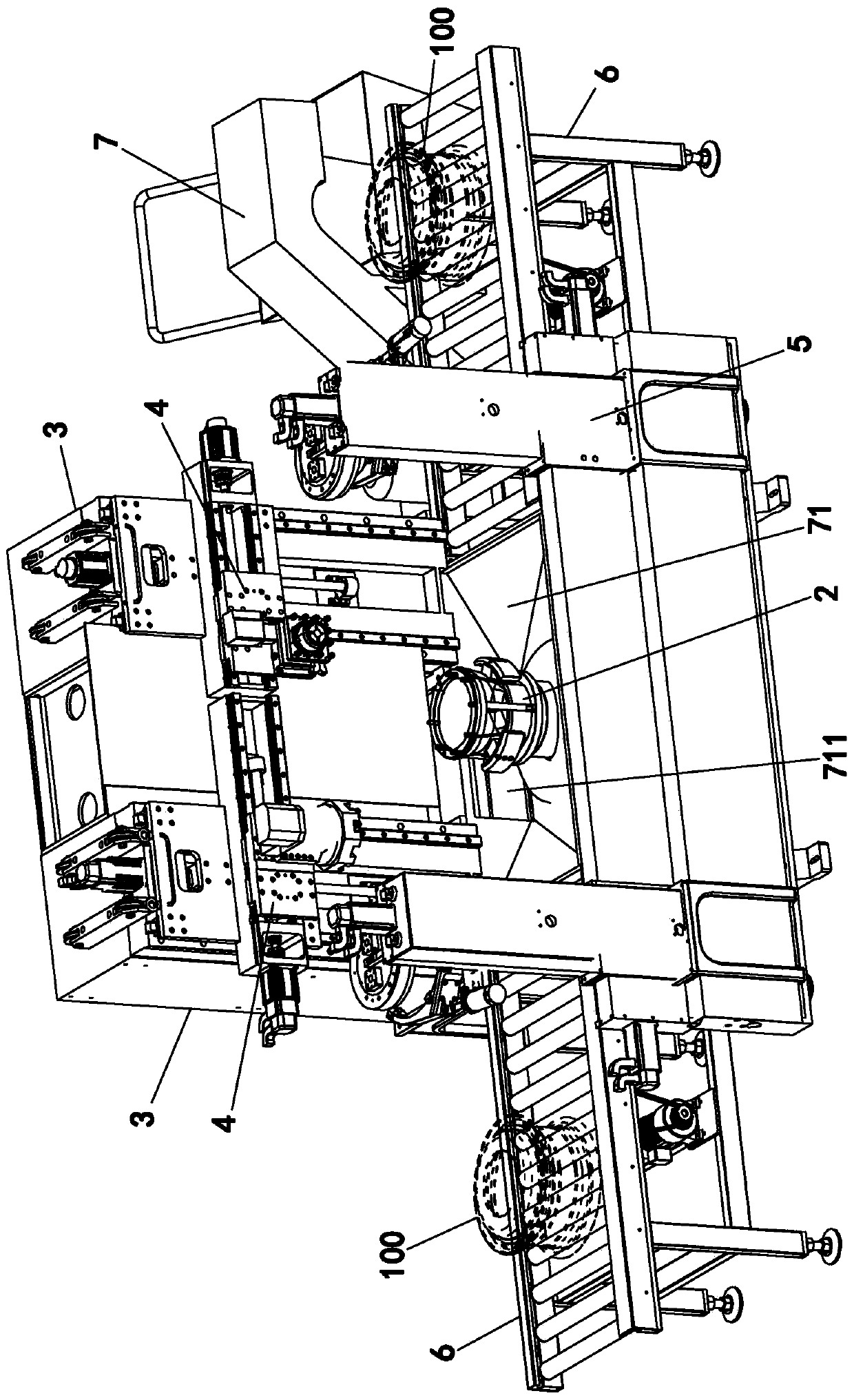
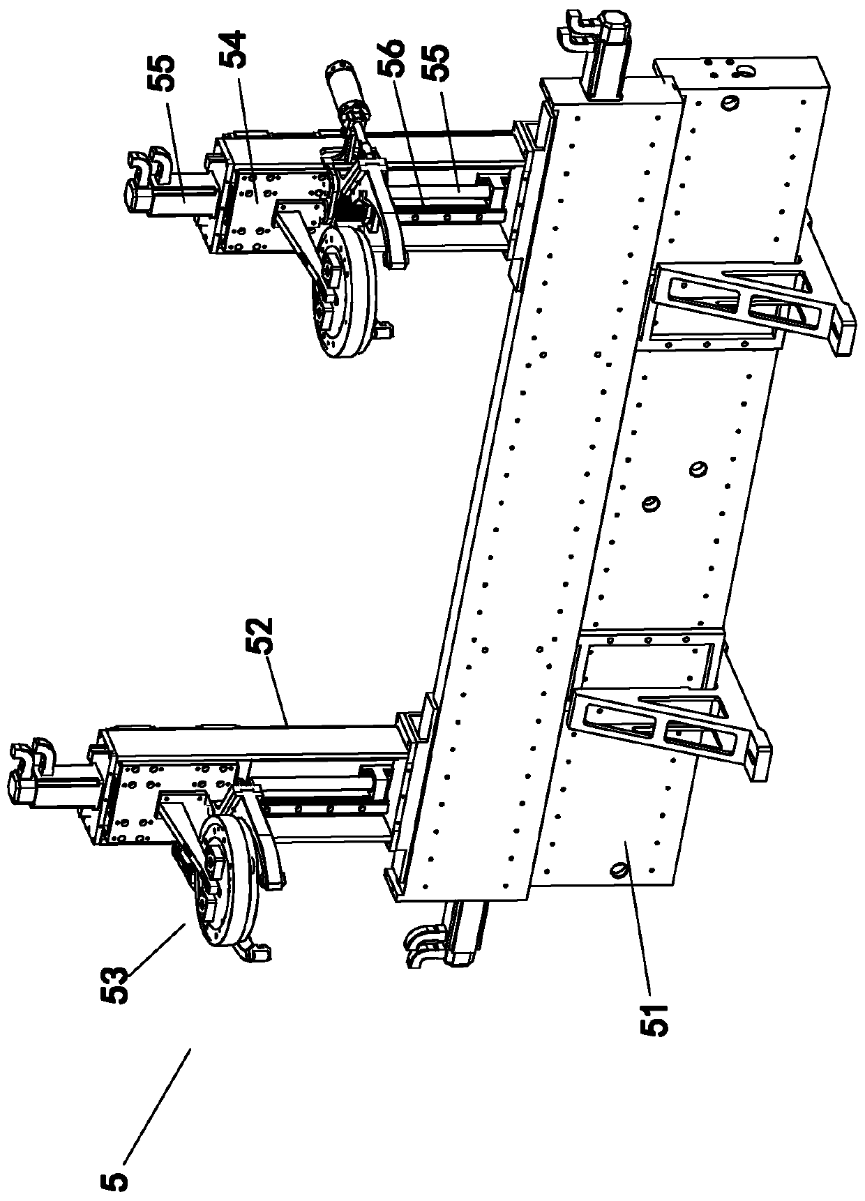
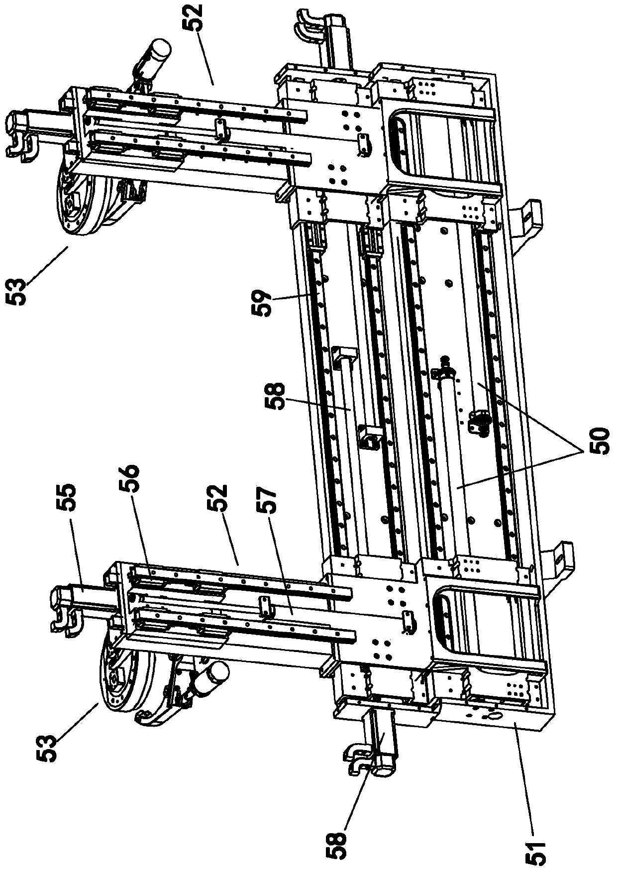
[0066] A CNC double-tool turning vertical lathe, such as figure 1 , Figure 8 with Picture 9 Shown, including base 1, bottom mold device 2, tool holder 3, turning tool set 4, manipulator assembly 5, conveyor 6, chain plate chip conveyor 7, protective cover 8 and numerical control system (not shown in the figure) . The operation of the whole machine is controlled by a numerical control system. The turning vertical lathe is suitable for turning processing of many industrial workpieces. The following workpieces are processed by taking the wheel as an example to describe the mechanical structure in detail. The numerical control system is the control, programming program and circuit connection part. No more detailed description.

[0067] The base 1, such as Image 6 with Figure 7 As shown, for the installation of ...


PUM


Abstract

The invention discloses a numerical control twin-cutter turning vertical lathe which comprises a base, a bottom die device, two cutter frames, two turning cutter groups and a numerical control system, wherein the bottom die device is arranged on the base and used for fixedly placing a workpiece, and the cutter frame is vertically connected to the base and arranged on one side of the bottom die device; each turning cutter group can slide relatively to each cutter frame and is used for turning the workpiece, and the numerical control system is used for controlling the operation work of the complete machine; the two cutter frames are arranged at intervals side by side; the two turning cutter groups are respectively arranged on the two cutter frames and can move relative to the bottom die device up and down and left and right. The numerical control twin-cutter turning vertical lathe can complete multiple turning processes for the workpiece through one-time fixation, and therefore the processing precision and the working efficiency are improved. The numerical control twin-cutter turning vertical lathe further comprises a mechanical arm assembly, and the mechanical automation operation effect can be improved.

Description

Technical field [0001] The invention relates to the field of machinery used for workpiece turning processing, in particular to a numerical control double-tool turning vertical lathe capable of simultaneous turning processing with two tools. Background technique [0002] Many industrial workpieces that require fine turning processing have to go through multiple processes and multiple turning machines for processing during the production and processing process. Since they are processed on different machines, they must be handled frequently and fixedly installed during the processing. , Workpiece disassembly, etc. [0003] For example, a car wheel has many places on its circumference that need to be turned, such as the outer bottom surface of the wheel, the inner and outer chamfers of the center hole, the outer circle of the lock groove, the outer circle of the rim, the lower end of the rim, and the inner and outer chamfers For other turning processing, the existing turning method is...

Claims


Application Information

Patent Timeline
Patent Type & Authority Patents(China)
IPC IPC(8): B23B5/28
CPCB23B5/28B23B2215/08
Inventor 许飞鹏康永强许家地
Owner 泉州市泰智机械发展有限公司
Learn More