Numerical control relief-grinding machine

A shovel grinder and lathe bed technology, applied in the field of numerical control processing equipment, can solve problems such as complex and frequent operations, restrictions on enterprise development, and shortage of technical operators

Inactive Publication Date: 2016-02-03
CHONGQING DACHENG GRACE NC TECH CO LTD
View PDF0 Cites 0 Cited by
  • Summary
  • Abstract
  • Description
  • Claims
  • Application Information

AI Technical Summary

Problems solved by technology

It is precisely because the operations are complex and frequent, and rely more on the technical experience of the workers, it often takes ten years and cannot guarantee to train a qualified operator. The shortage of technical operators in this sequence restricts the development of the enterprise.

Method used


Image

  • Numerical control relief-grinding machine

Examples


Embodiment Construction

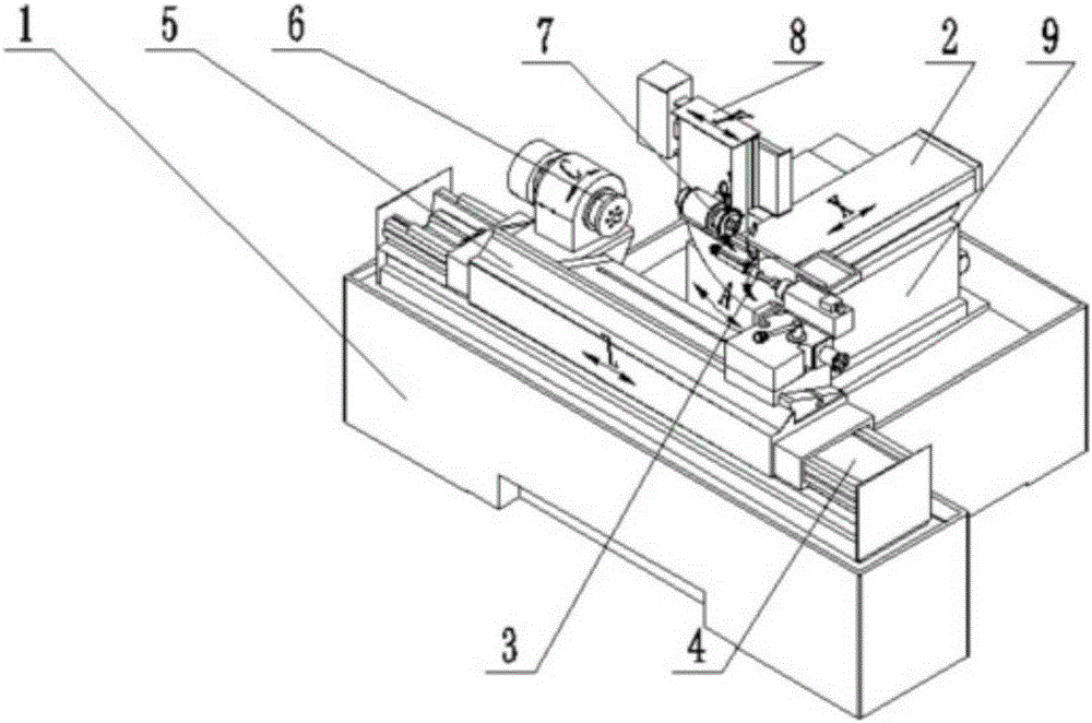
[0015] This example figure 1 As shown, a numerically controlled shovel grinder, which includes a cast-shaped zigzag-shaped lathe bed 1, said lathe bed 1 is provided with a Z-direction motion device 5 and a rotary table that move along the Z-direction of the lathe bed 1 Part 9, the Z-direction motion device 5 includes a Z-direction base 5-7, the Z-direction base 5-7 is arranged on the lathe bed 1, and the Z-direction base 5-7 is equipped with a motor 5-5 and a linear motor composed of a motor magnetic plate 5-6, the linear motor provides driving force to drive the Z-direction sliding table 5-1 to move along the linear guide rail 5-4 provided with the guide rail slider 5-3, the The Z sliding table 5-1 is provided with an indexing part 6, a tailstock 4 and a Z-direction grating 5-2;

[0016] The said rotary table part 9 includes a rotary table 9-1, and the said rotary table 9-1 is arranged on the rotary base 9-3 installed on the machine bed 1, and said rotary work The platform ...


PUM


Abstract

The invention discloses a numerical control relief-grinding machine and relates to the field of numerical control machining equipment. A machine body of the numerical control relief-grinding machine is provided with a Z-direction movement device and a rotary workbench. The rotary workbench is provided with an X-direction movement device and a Y-direction movement device, and the X-direction movement device and the Y-direction movement device can rotate along with the rotation of the rotary workbench. According to the numerical control relief-grinding machine, the Z-direction movement device, the X-direction movement device and the Y-direction movement device are driven by linear motors and locate movement in coordination with rasters, so that the accuracy of movement is improved. An indexing component is provided with a circular raster, and a closed loop is formed to accurately locate rotational movement. According to the numerical control relief-grinding machine, the direct driving motor technology and the closed loop control technology are adopted to reduce kinematic errors generated in the movement process of the machine and shorten the relief-grinding dressing time.

Description

technical field [0001] The invention relates to the field of numerical control processing equipment, in particular to a numerical control relief grinder which adopts direct-drive motor technology and closed-loop control technology to reduce motion errors generated during machine tool movement and shorten relief grinding and dressing time. Background technique [0002] The relief grinding wheel of the traditional hob relief grinding machine is manually trimmed with a slide rule. When dressing the grinding wheel, the operator firstly adjusts the position of the slide rule according to the experience, roughs it for a trial grinding, then adjusts the position of the slide rule according to the grinding result, then dresses the grinding wheel again, tries grinding it, and then adjusts the position of the slide rule according to the grinding result. Adjust the position of the slider, and trim the grinding wheel again. Repeat this until it is accurate. The qualified rate is very lo...

Claims


Application Information

Patent Timeline
Patent Type & Authority Applications(China)
IPC IPC(8): B24B3/12B24B3/00B24B47/04B24B47/12B24B27/00
CPCB24B3/12B24B3/00B24B27/0076B24B47/04B24B47/12
Inventor 许林
Owner CHONGQING DACHENG GRACE NC TECH CO LTD
Why Eureka
Try Eureka