High-performance engine inlet valve and preparing method thereof
An intake valve and valve technology, applied in engine components, machines/engines, mechanical equipment, etc., can solve problems such as incompetence, and achieve the effect of ensuring high temperature resistance, reducing equipment investment, and excellent high temperature performance
- Summary
- Abstract
- Description
- Claims
- Application Information
AI Technical Summary
Problems solved by technology
Method used
Image
Examples
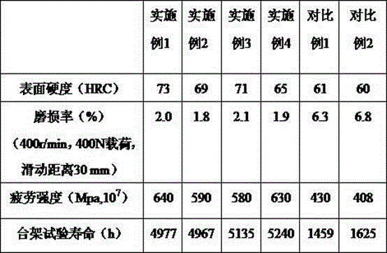
Embodiment 1
[0026] (1) Prepare the ingredients according to the alloy composition range, C: 0.30%; Si: 0.1%; Mo: 0.17%; Mn: 0.5%; Cr: 1.04%; W: 0.93%; Ce: 0.11%; Nb: 0.06%; Cu: 0.08%. Mix the alloy materials evenly;
[0027] (2) Smelting in a vacuum induction furnace with the temperature controlled at 1650°C for 2.5 hours;
[0028] (3) Perform three forgings at 1100°C, 1050°C, and 950°C respectively, and control the deformation ratio to 70% to obtain the intake valve blank;
[0029] (4) Insulate at 820°C for 1.5h, quench, then heat to 450°C, hold for 2 hours, and finally air cool;
[0030] (5) Remove the surface oxide skin, perform smooth treatment, and then perform surface ultrasonic treatment. Ultrasonic treatment is carried out at room temperature and the frequency is controlled at 30,000 Hz, followed by nitriding treatment at 350°C;
[0031] (6) Use milling machine to process the surface finish of the cone surface;
[0032] (7) Surfacing molybdenum-zirconium alloy on the cone surf...
Embodiment 2
[0035] (1) Prepare the ingredients according to the alloy composition range, C: 0.35%; Si: 0.05%; Mo: 0.14%; Mn: 0.75%; Cr: 0.87%; W: 1.0%; Ce: 0.1%; Nb: 0.1%; Cu: 0.05%. Mix the alloy materials evenly;
[0036] (2) Smelting in a vacuum induction furnace with the temperature controlled at 1650°C for 2 hours;
[0037] (3) Perform three forgings at 1100°C, 1050°C, and 950°C respectively, and control the deformation ratio to 72% to obtain the intake valve blank;
[0038] (4) Insulate at 800°C for 1.5h, quench, then heat to 500°C, hold for 2 hours, and finally air cool;
[0039] (5) Remove the surface oxide skin, perform smooth treatment, and then perform surface ultrasonic treatment. Ultrasonic treatment is carried out at room temperature and the frequency is controlled at 30,000 Hz, and then nitriding treatment is carried out at 330°C;
[0040] (6) Use milling machine to process the surface finish of the cone surface;
[0041] (7) Surfacing molybdenum-zirconium alloy on the co...
Embodiment 3
[0044] (1) Prepare the ingredients according to the alloy composition range, C: 0.40%; Si: 0.065%; Mo: 0.2%; Mn: 0.80%; Cr: 0.80%; W: 0.9%; Ce: 0.2%; Nb: 0.05%; Cu: 0.1%. Mix the alloy materials evenly;
[0045] (2) Smelting in a vacuum induction furnace with the temperature controlled at 1620°C for 2 hours;
[0046] (3) Perform three forgings at 1100°C, 1050°C, and 950°C respectively, and control the deformation ratio to 73% to obtain the intake valve blank;
[0047] (4) Insulate at 850°C for 1 hour, quench, then heat to 500°C, hold for 2.5 hours, and finally air cool;
[0048] (5) Remove the surface oxide skin, perform smooth treatment, and then perform surface ultrasonic treatment. Ultrasonic treatment is carried out at room temperature and the frequency is controlled at 35,000 Hz, followed by nitriding treatment at 360°C;
[0049] (6) Use milling machine to process the surface finish of the cone surface;
[0050] (7) Surfacing molybdenum-zirconium alloy on the cone sur...
PUM
| Property | Measurement | Unit |
|---|---|---|
| thickness | aaaaa | aaaaa |
| thickness | aaaaa | aaaaa |
| heat deflection temperature | aaaaa | aaaaa |
Abstract
Description
Claims
Application Information
 - R&D
- Intellectual Property
- Life Sciences
- Materials
- Tech Scout
- Unparalleled Data Quality
- Higher Quality Content
- 60% Fewer Hallucinations
Browse by: Latest US Patents, China's latest patents, Technical Efficacy Thesaurus, Application Domain, Technology Topic, Popular Technical Reports.
© 2025 PatSnap. All rights reserved.Legal|Privacy policy|Modern Slavery Act Transparency Statement|Sitemap|About US| Contact US: help@patsnap.com

