Flue gas reheating system based on phase-change heat transfer and fluoroplastic technologies

A technology of flue gas reheating and phase change heat, applied in the field of flue gas reheating system, can solve the problems of reducing the height and scope of flue gas emission diffusion, affecting power plant operation and related evaluation, increasing unit maintenance and repair costs, etc. The effect of promoting normal work, avoiding acid dew corrosion, and reducing maintenance costs

Inactive Publication Date: 2016-02-03
SHANGHAI HUAXIANG ENERGY SAVING & ENVIRONMENTAL PROTECTION CO LTD
View PDF8 Cites 0 Cited by
  • Summary
  • Abstract
  • Description
  • Claims
  • Application Information

AI Technical Summary

Problems solved by technology

However, after the wet desulfurization of the flue gas, the temperature of the flue gas drops to a low level, resulting in the condensation of acid dew in the flue gas, which will corrode and damage the inner wall of the flue and chimney, causing irreparable damage and reducing the reliability of the unit. It shortens the maintenance cycle of the unit, increases the maintenance cost of the unit, and reduces the power generation and income of the unit; in addition, if the low-temperature flue gas after desulfurization is directly discharged into the atmosphere through the chimney, the flue gas Insufficient discharge power will increase the difficulty of chimney discharge and reduce the diffusion height and range of flue gas discharge; it is easy to form gypsum rain and acid droplet settlement around the power plant, causing serious damage to the surrounding environment of the power plant and affecting the power plant. Operation and related evaluation

Method used


Image

  • Flue gas reheating system based on phase-change heat transfer and fluoroplastic technologies
  • Flue gas reheating system based on phase-change heat transfer and fluoroplastic technologies

Examples


Embodiment Construction

[0024] The idea, specific structure and technical effects of the present invention will be further described below in conjunction with the accompanying drawings, so as to fully understand the purpose, features and effects of the present invention.

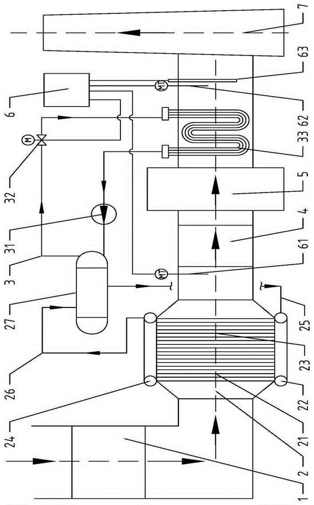
[0025] Such as figure 1 As shown, the flue gas reheating system of the present invention is arranged at the tail of the flue of the boiler, and the tail of the flue and the chimney 7 are sequentially provided with a final air preheater 1, a dust collector 4 and a desulfurization tower 5, and the dust collector 4 The flue gas outlet is connected to the flue gas inlet of the desulfurization tower 5. The flue gas reheating system includes a phase change waste heat recovery module 2 for recovering the waste heat of the flue gas, a fluoroplastic reheating module 3 for reheating the low-temperature flue gas after desulfurization, and a reheating module for reheating the flue gas An automatic control module 6 for automatic control of the...


PUM


Abstract

The invention discloses a flue gas reheating system based on phase-change heat transfer and fluoroplastic technologies. The flue gas reheating system is arranged at the tail of a flue of a boiler; a last stage air preheater, a dust remover and a desulfurizing tower are sequentially arranged between the tail of the flue and a chimney; and a flue gas outlet of the dust remover is connected with a flue gas inlet of the desulfurizing tower. The flue gas reheating system comprises a phase-change waste heat recovering module for recovering waste heat of flue gas, a fluoroplastic reheating module for reheating the low temperature flue gas after desulfuration, and an automatic control module for automatically controlling the flue gas reheating system integrally, wherein the phase-change waste heat recovering module is arranged in the flue between the last stage air preheater and the dust remover, and the fluoroplastic reheating module is arranged in the flue between the desulfurizing tower and the chimney. Compared with the prior art, the flue gas reheating system has the advantages of good waste heat recovering performance, adjustability, controllability, stability, reliability, good reheating performance, corrosion resistance, little energy consumption, etc.; flue gas discharge power of the boiler is improved greatly; and the surrounding environment of a power plant is improved.

Description

technical field [0001] The invention relates to a flue gas reheating system, in particular to a flue gas reheating system based on phase conversion heat and fluoroplastic technology. The flue gas reheating system can improve the utilization rate of flue gas waste heat and increase the power of boiler exhaust. It is mainly used in tail flue systems such as thermal power boilers, industrial kilns, and heating furnaces. Background technique [0002] Due to the changeable composition of the coal used, the actual operating exhaust gas temperature in existing thermal power plants in China often does not reach the design value, resulting in a decrease in the actual operating efficiency of the boiler; The normal operation of the dust collector affects the working efficiency and service life of the dust collector, and reduces the operation stability of the unit. [0003] In addition, the existing thermal power plants in operation generally adopt the wet desulfurization technology, a...

Claims


Application Information

Patent Timeline
Patent Type & Authority Applications(China)
IPC IPC(8): F23J15/06F23J15/02
CPCY02E20/30
Inventor 赵恒亮董建东
Owner SHANGHAI HUAXIANG ENERGY SAVING & ENVIRONMENTAL PROTECTION CO LTD
Why Eureka
Try Eureka