RFID reader wave beam switching type array antenna

An array antenna and beam switching technology, which is applied in the direction of antenna, antenna support/installation device, electrical components, etc., can solve the problems of reducing reader coverage, reducing beam width, increasing transmission power, etc., to achieve enhanced gain and reduced The effect of small antenna size and reduced backlobe level

Inactive Publication Date: 2016-02-03
TIANJIN POLYTECHNIC UNIV
View PDF0 Cites 12 Cited by
  • Summary
  • Abstract
  • Description
  • Claims
  • Application Information

AI Technical Summary

Problems solved by technology

[0006] When the receiving power of the tag antenna remains unchanged, increasing the recognition distance requires increasing the transmitting power or increasing the gain of the reader antenna. The increase in the gain of a single-beam or fixed multi-beam antenna reduces the beam width and reduces the coverage of the reader.

Method used


Image

  • RFID reader wave beam switching type array antenna
  • RFID reader wave beam switching type array antenna
  • RFID reader wave beam switching type array antenna

Examples


Embodiment Construction

[0018] In order to make the object, technical solution and advantages of the present invention clearer, the embodiments of the present invention will be further described in detail below in conjunction with the accompanying drawings.

[0019] The gist of the present invention is to propose a beam-switching array antenna to realize the effective identification of tags by readers and expand the identification area of ​​readers. The proposed antenna array has important guiding significance for the shortcomings of readers such as short recognition distance, small recognition area, and high price.

[0020] The embodiments of the present invention will be further described in detail below in conjunction with the accompanying drawings.

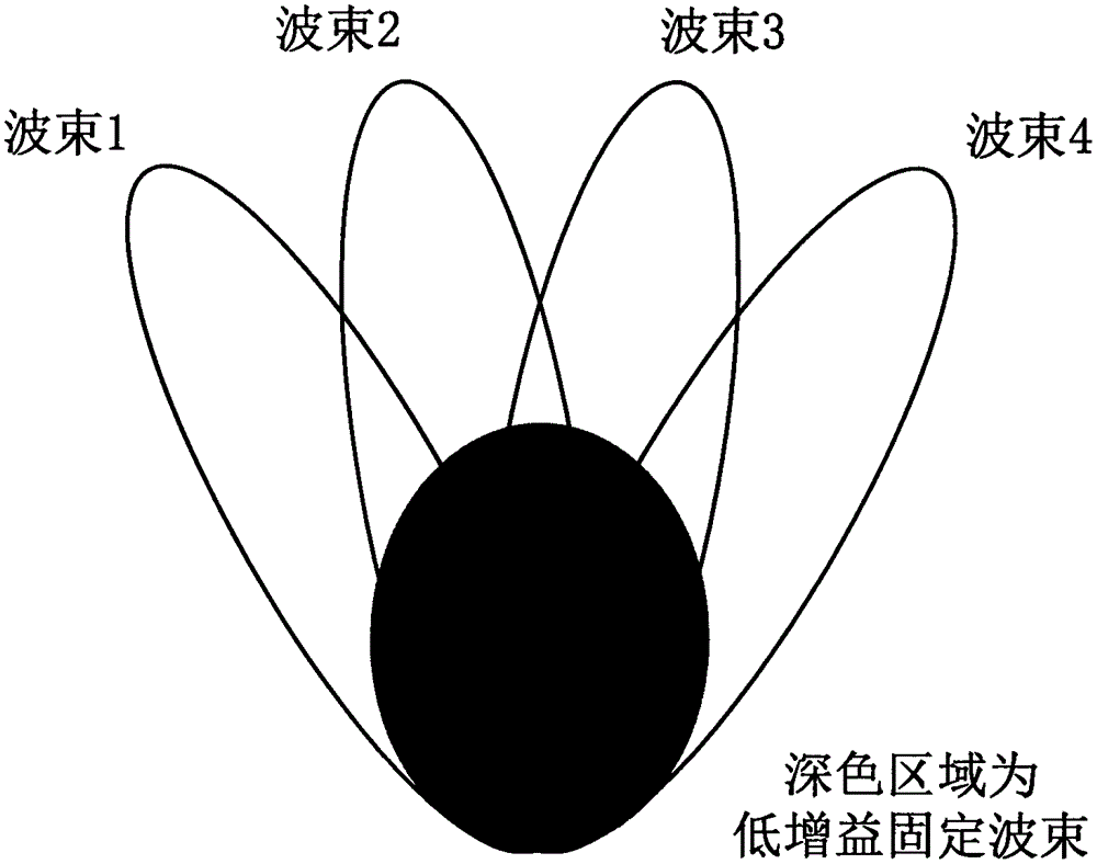
[0021] figure 1 It is a schematic diagram of the reader beam switching antenna scanning. When the receiving power of the tag antenna remains unchanged, increasing the recognition distance requires increasing the transmission power or increasing the ...


PUM


Abstract

The invention relates to an RFID reader wave beam switching type array antenna and belongs to the radio frequency identification technology and antenna technology field. The RFID reader wave beam switching type array antenna comprises four antenna radiation units, an electrical control phase shifter, a power divider and an attenuator, wherein the antenna radiation units employ a microstrip antenna mode to realize miniaturization of reader antennas, a radiation paster is provided with a groove, a dielectric layer is an air layer, a grounding face is a flat bonded copper, a coaxial line feeding mode is utilized, phase control on an output signal can be realized by the electrical control phase shifter through a main chip, so the wave beam switching function is realized; the power divider is a quartering power divider formed by microstrip lines, the power divider is independently designed, the structure is simple, mounting is convenient, debugging is easy, amplitude attenuation for a signal current can be carried out through an attenuator, so the excitation amplitude proportion is satisfied. According to the RFID reader wave beam switching type array antenna, area scanning for labels can be carried out through a reader, the identification area of the reader is expanded, and guidance meaning is exerted on the RFID system.

Description

technical field [0001] The invention belongs to the field of radio frequency identification technology and antenna technology, in particular to a reader beam switching array antenna. Background technique [0002] RFID (Radio Frequency Identification) technology uses radio frequency signals to conduct non-contact two-way communication, automatically identify target objects and obtain relevant information data, and has been successfully applied in various fields such as manufacturing, logistics and warehousing, transportation, medical and health, and public safety. It uses the spatial coupling of radio frequency signals to realize contactless data transmission, and achieves the purpose of identifying objects through the mutual transmission of information. [0003] The maximum recognition distance of commonly used readers is about 10 meters, and the total recognition area is limited, which cannot meet the needs of most users, thus limiting its large-scale application. As an im...

Claims


Application Information

Patent Timeline
Patent Type & Authority Applications(China)
IPC IPC(8): H01Q1/22H01Q23/00
Inventor 李建雄陈明省闫必行宋山林蒋昊林
Owner TIANJIN POLYTECHNIC UNIV
Why Eureka
Try Eureka