Plasma processing apparatus

a processing apparatus and plasma technology, applied in the direction of plasma technique, coating, electric discharge lamps, etc., can solve the problems of poor matching conditions of matching circuits, increased manufacturing costs, increased weight of apparatuses, etc., and achieve the effect of improving the power withstand resistance of coaxial lines

Inactive Publication Date: 2001-03-13
ANELVA CORP
View PDF6 Cites 39 Cited by
  • Summary
  • Abstract
  • Description
  • Claims
  • Application Information

AI Technical Summary

Benefits of technology

In FIG. 4, the upper surface 96 of the bottom-plate 46a is a downwardly convex truncated conical surface, and its transverse cross sectional form is that of a straight line which is inclined downward toward the center. The angle of inclination with respect to the bottom surface (the horizontal surface) of the large diameter part 56 of the cathode electrode 54 is within the range from about 0 to 30 degrees. With such a construction, the radial line which is formed by the lower surface of the large diameter part 56 of the cathode 54 and the upper surface 96 of the bottom-plate 46a is such that the gap spacing becomes wider toward the center. That is to say, this radial line is such that the impedance value increases towards the inside. Consequently, the characteristic impedance value of the small diameter coaxial line which should be impedance matched at the inner end part of the radial line can also be raised. If the characteristic impedance value of the small diameter coaxial line can be raised, then the gap 74 between the small diameter part 58 and the second wall 68 can be widened and the power withstand resistance of the coaxial line is improved and, at the same time, matching with a power source side cable which has a characteristic impedance of 50 .OMEGA. is also facilitated.

Problems solved by technology

In this case, rigorously, Z.sub.0 is not equal to Z.sub.L and the line length L has an effect, and the matching conditions of the matching circuit become poor.
Hence, the diameter of the cathode 18 has to be increased and, as a result, the weight of the apparatus is increased and there is a further problem in that the manufacturing costs are also increased.

Method used


Image

  • Plasma processing apparatus
  • Plasma processing apparatus
  • Plasma processing apparatus

Examples


Embodiment Construction

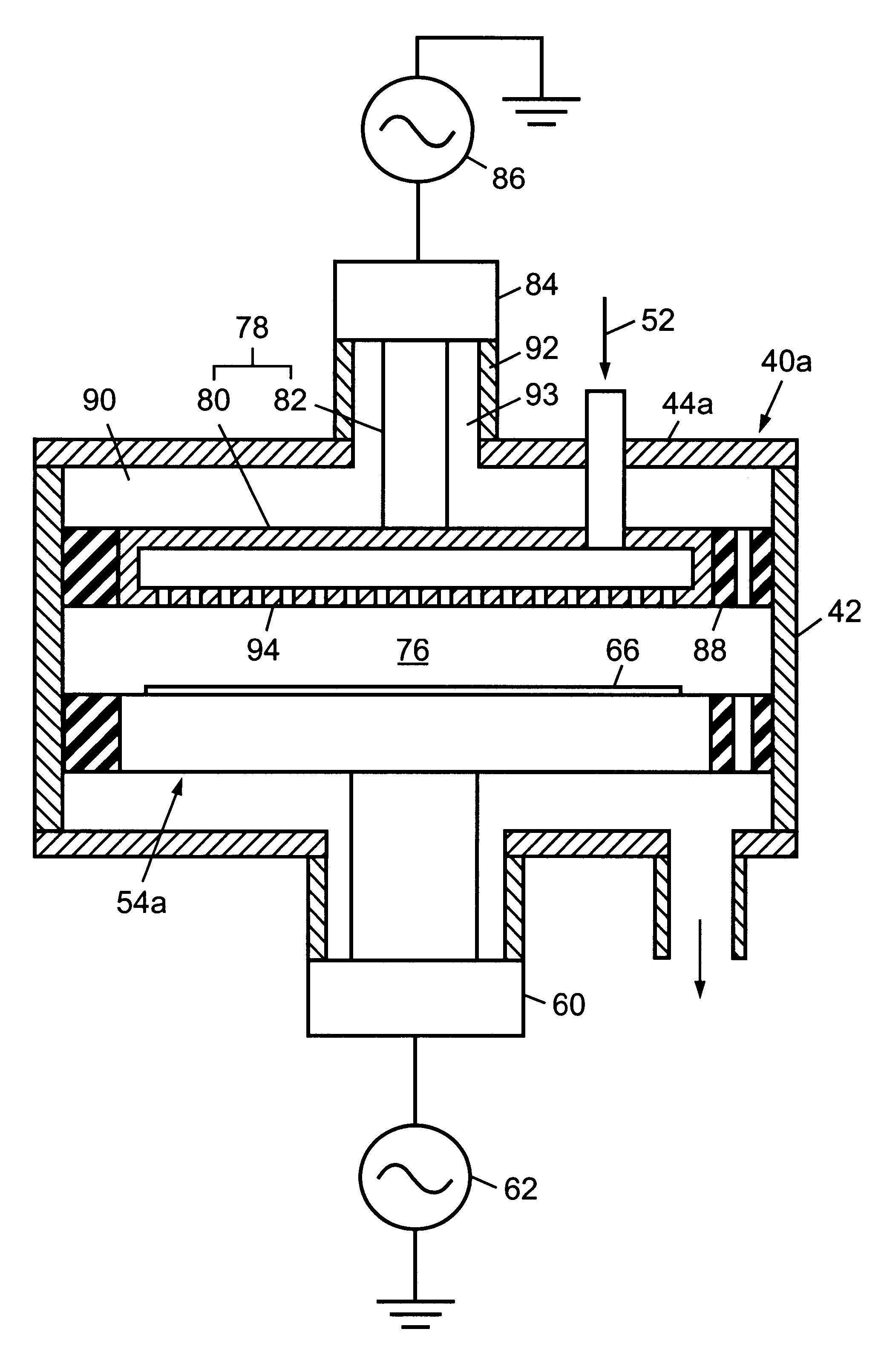
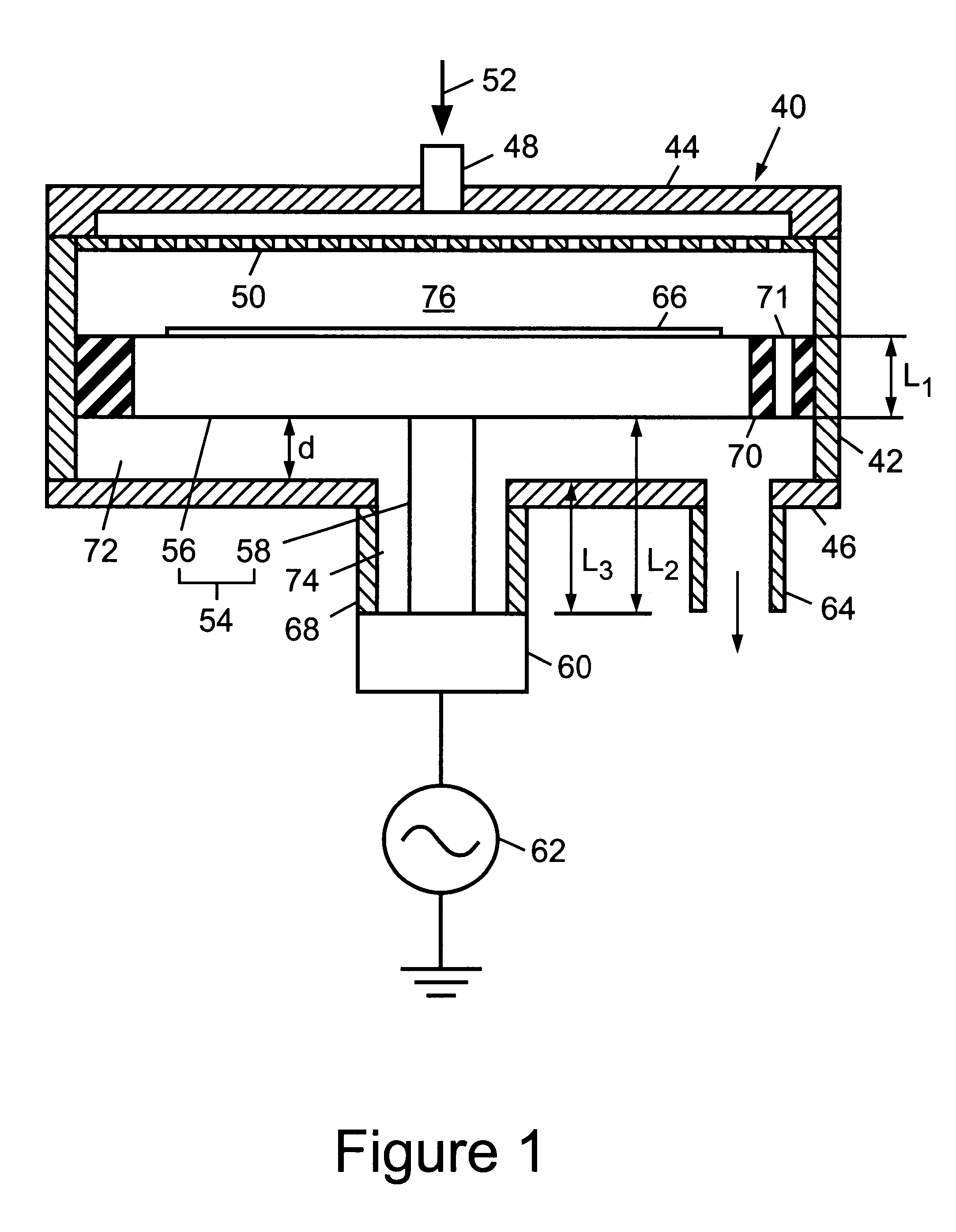
An example of the design of plasma processing apparatus as shown in FIG. 1 is described below with reference to FIG. 6. The design of plasma processing apparatus for processing 8 inch wafers using a VHF band frequency of 60 MHZ is described as an example below. The radius of the outer circumferential surface of the small diameter part 58 of the cathode 54 is r.sub.1, the radius of the inner circumferential surface of the second wall 68 is r.sub.2, the radius of the outer circumferential surface of the large diameter part 56 of the cathode 54 is r.sub.3 and the radius of the inner circumferential surface of the first wall 42 is r.sub.4. Quartz (relative dielectric constant .di-elect cons..sub.r -3.78) is used for the insulator 70.

First of all, assume that the diameter of the large diameter part 56 of the cathode 54 (the part on which the substrate is mounted) is 280 mm (r.sub.3 =140 mm), the length L.sub.1 of the large diameter part 56 is 60 mm and the length L.sub.3 of the part surr...


PUM

PropertyMeasurementUnit
frequencyaaaaaaaaaa
angleaaaaaaaaaa
diameteraaaaaaaaaa

Abstract

A plasma processing apparatus includes a cathode 54 having a large diameter part 56 and a long thin small diameter part 58, and the upper end surface of the large diameter part 56 faces the plasma forming space 76. The substrate 66 which is to be processed is mounted on the upper end surface of the large diameter part 56. The lower end of the small diameter part 58 is connected via the matching circuit 60 to the high frequency power source 62. The transmission path within the chamber comprises a large diameter coaxial line, a small diameter coaxial line and a radial line which connects them. The large diameter coaxial line includes the large diameter part 56, the first side wall 42 and the insulator 70. The radial line includes the lower surface of the large diameter part 56, the upper surface of the bottom plate 46 and the gap 72 between them. The small diameter coaxial line includes the small diameter part 58, the second side wall 68 and the gap 74. Appropriate impedance matching is achieved between the two coaxial lines and the radial line.

Description

CROSS-REFERENCE TO RELATED APPLICATIONThis application claims the priority of Japanese Patent Application No. 10-111401, filed on Apr. 8, 1998, the contents of which are hereby incorporated herein by reference.1. Field of the InventionThe invention concerns apparatus in which CVD (chemical vapor deposition) or etching, for example, is executed using plasma, and in particular it concerns plasma processing apparatus which is characterized by the construction of the transmission path by which the high frequency power is supplied to the plasma.2. Discussion of Related ArtSurface processing such as CVD and etching is carried out widely using plasma at the present time, and LSI (large scale integrated circuits) and FPD (flat panel devices) are being manufactured using such techniques. Various systems are known for generating the plasma, but the plasma generating systems in which a high frequency discharge is used are widely employed because they enable a stable plasma to be obtained over ...

Claims


Application Information

Patent Timeline
Patent Type & Authority Patents(United States)
IPC IPC(8): H01J37/32C23C16/50H05H1/46C23F4/00H01L21/205H01L21/302H01L21/3065
CPCH01J37/32082H01J37/32183
Inventor SATO, HISAAKITSUKADA, TSUTOMUMIZUNO, SHIGERUTSUCHIYA, NOBUAKI
Owner ANELVA CORP
Why Eureka
Try Eureka