
Continuous vacuum frying oil removing machine

A vacuum frying and deoiling machine technology, applied in oil/fat roasting and other directions, can solve the problems of prolonged shelf life, inability to further reduce processing costs, limitation of processing varieties, etc., to reduce the damage of nutrients, improve repeated utilization, The effect of compaction and easy maintenance

Inactive Publication Date: 2016-02-10
陈长清
View PDF11 Cites 14 Cited by
  • Summary
  • Abstract
  • Description
  • Claims
  • Application Information

AI Technical Summary

Problems solved by technology

Due to the high oil temperature, the processed products have poor nutritional value and are prone to produce toxic substances. Eating too much can easily make the body fat. The shelf life of the product is not long, and the production cost is high, wasting energy and oil.
[0004] Atmospheric pressure fryer and atmospheric continuous fryer equipment process food with an oil temperature of 180°C to 250°C or even higher, and the oil content of the finished product is above 30%. The vertical vacuum fryer deoiler equipment belongs to the prior art Widely used processing equipment, the temperature of processed food is generally 90 ° C ~ 140 ° C, and the oil content of the finished product is 15% ~ 20%. The processing temperature has changed in terms of nutrition, taste, color, etc. Although the oil content of the finished product has been reduced, the cost has been reduced, and the shelf life has been extended, but because it cannot work continuously and automatically, the processing cost cannot be further reduced, and the oil residue cannot be removed at any time. , long-term processing of food in unclean oil will cause food pollution, and there are some restrictions on processing varieties, so the promotion and application of this equipment is limited.

Method used


Image

  • Continuous vacuum frying oil removing machine
  • Continuous vacuum frying oil removing machine
  • Continuous vacuum frying oil removing machine

Examples


Embodiment Construction

[0033] Below in conjunction with accompanying drawing, further describe structure and working process of the present invention by embodiment:

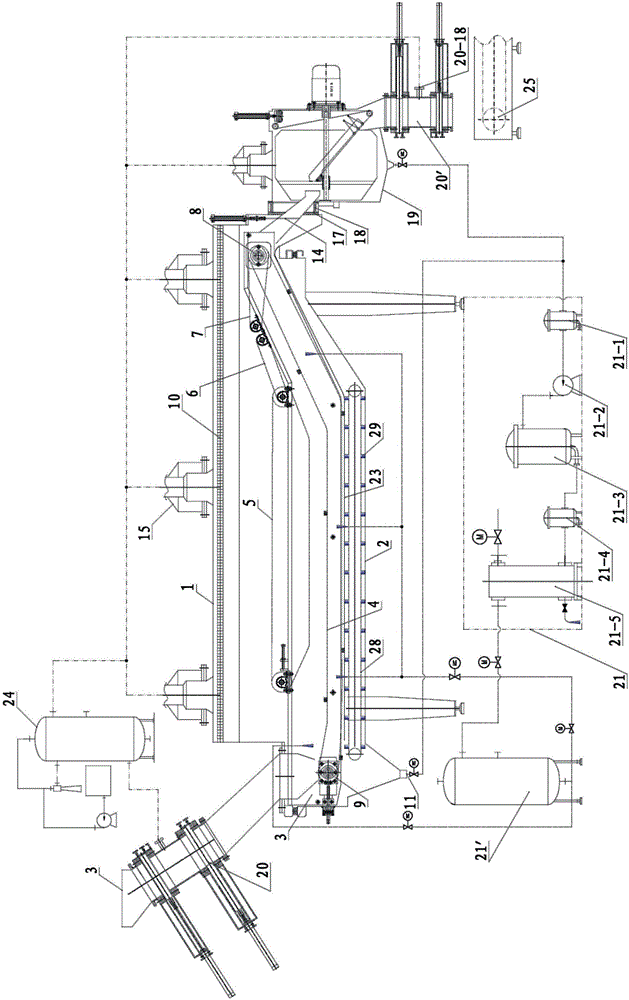
[0034] figure 1 It is a schematic diagram of the overall structure of a continuous vacuum frying and deoiling machine of the present invention, which is suitable for vacuum frying processing equipment with various varieties and large output.

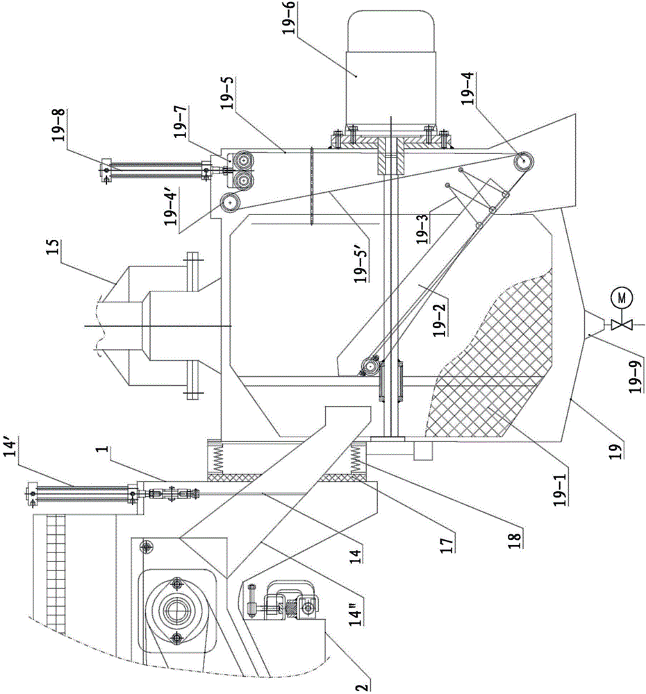
[0035] Its working process is: the bulk material enters through the feed port (3) of the feed sealing device (20), and the air in the bulk material is evacuated to a certain level in the feed sealing device (20) through the pre-vacuum port (20-18). After the vacuum degree is reached, the bulk material falls from the outlet (20-12) of the feeding sealing device (20) onto the material conveying mesh belt (4) in the frying chamber, and after a period of dehydration, the material floats upwards. The floating material runs forward under the drive of the pressing mesh belt (5), and the material after ...


PUM


Abstract

The invention relates to a continuous vacuum frying oil removing machine capable of maintaining high-vacuum-degree stability under the continuous feeding and discharging conditions. The machine is provided with an upper frying bin, a lower frying bin, a wedge disc type feeding and discharging sealing device, a centrifugal oil removing machine device, a vacuum system, an oil filtering device, a cleaning system and an upper frying bin pressurizing device. The wedge disc type feeding and discharging sealing device is adopted as a feeding and discharging sealing device, or two vacuum valves are adopted to be combined into the feeding and discharging sealing device. The simple and high-speed centrifugal oil removing machine device is adopted. The machine is simple in structure, low in manufacturing cost, convenient to press and maintain, wide in application range, suitable for continuous vacuum frying processing of fruits, vegetables, dried fruits, cooked wheaten foods, aquatic products, livestock and poultry meat and other foods, applicable to frying processing equipment in large or medium or small food processing enterprises and large collective canteens, also applicable to continuous vacuum impregnating and capable of being wholly and automatically controlled.

Description

technical field [0001] The invention relates to a continuous vacuum frying and deoiling machine which can continuously maintain the stability of high vacuum degree under the condition of continuous feeding and discharging. The frying and deoiling processing equipment belongs to the field of food processing machinery manufacturing. Background technique [0002] In the prior art, CN20102052739.2 patents a continuous vacuum frying and deoiling machine using a drum-type feeding method. The fried processing product is single and cannot be adapted to the processing of many varieties. The structure is complex and the manufacturing cost is high. Centrifugal deoiling machine The noise is big when working, and the problem that the service time is not long in the vacuum sealing device and the like still needs to be further solved, and it cannot adapt to the different needs of different types of frying enterprises. [0003] The usual frying method is atmospheric pressure and high temp...

Claims


Application Information

Patent Timeline
IPC IPC(8): A21B5/08
Inventor 陈长清
Owner 陈长清
Learn More