Infrared heating testing device and testing method for bituminous pavement

A heating test, asphalt pavement technology, applied in the field of highway engineering, can solve the problems of immature asphalt pavement technology, reduced asphalt recyclability, reduced work efficiency, etc., to avoid incomplete heating, less consumption, and easy operation.

Inactive Publication Date: 2016-02-10
CHANGAN UNIV
View PDF6 Cites 18 Cited by
  • Summary
  • Abstract
  • Description
  • Claims
  • Application Information

AI Technical Summary

Problems solved by technology

Among them, when using infrared radiation to heat the diseased asphalt pavement, the device that generates infrared rays needs to burn petroleum liquefied gas fuel to heat the alloy grid. When the temperature of the alloy grid reaches a certain level, it will emit infrared rays, and then irradiate the old asphalt pavement Heating, however, the energy consumption in this process is relatively large, because the technology of heating asphalt pavement by infrared radiation is not yet mature
[0003] In the process of using infrared radiation to heat the old asphalt pavement, if the heating time is too long or the intake of liquefied petroleum gas is too large, too much heat will be generated, which may cause the surface temperature of the old asphalt pavement to be too high and the performance to deteriorate. The more serious situation is that the asphalt on the surface catches fire and carbonizes and hardens, which greatly reduces the renewability of asphalt, not only wastes resources, pollutes the environment, but also greatly reduces work efficiency

Method used


Image

  • Infrared heating testing device and testing method for bituminous pavement
  • Infrared heating testing device and testing method for bituminous pavement
  • Infrared heating testing device and testing method for bituminous pavement

Examples


Embodiment Construction

[0036] The present invention will be further explained below in conjunction with specific embodiments and accompanying drawings.

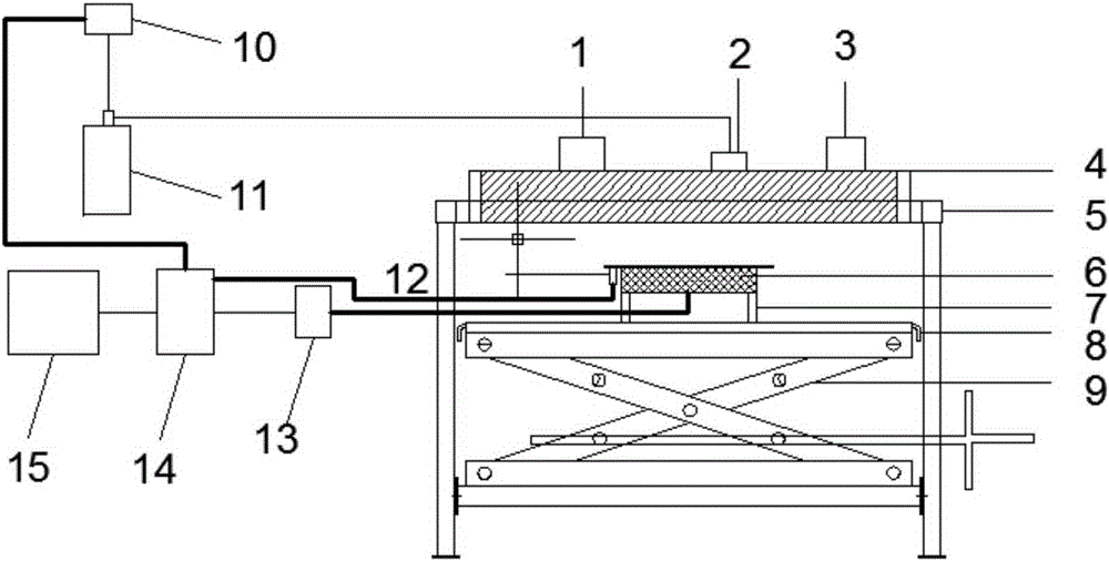
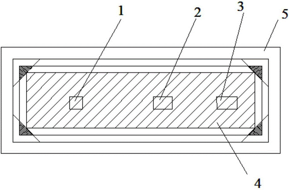
[0037] see figure 1 and figure 2 , the device of the present invention includes an infrared generation controller 1, a liquefied petroleum gas intake control valve 2, a frequency conversion blower 3, an infrared generating device 4, a test bench frame 5, a test block tray 7, an insulating water tank 8, a lifting device 9, a load Sensor 10, petroleum liquefied gas storage tank 11, infrared radiation flow sensor 12, thermocouple temperature compensation block 13, data acquisition instrument 14 and computer 15, wherein, infrared generation controller 1 controls the start and stop of infrared generation device 4; petroleum liquefaction Air intake control valve 2 controls the intake of liquefied petroleum gas; variable frequency blower 3 controls the intake of air; the asphalt test block 6 is installed on the test block tray 7 during the test, between...


PUM

PropertyMeasurementUnit
sizeaaaaaaaaaa

Abstract

The invention discloses an infrared heating testing device and testing method for bituminous pavement, and aims to enable the measured test data conclusion to play a theoretical guiding function on practice, and further enable the accuracy to be high, the simulation performance to be high and operation to be simple; the infrared heating testing device comprises a test bed framework, wherein an infrared ray generation device is arranged on the test bed framework; the infrared ray generation device is connected with an infrared ray generation controller, a liquefied petroleum gas inlet control valve and a variable-frequency air blower; the liquefied petroleum gas inlet control valve is connected to a liquefied petroleum gas source; the variable-frequency air blower is connected with an air source; a test block tray used for placement of a pitch test block is arranged at the lower end of the infrared ray generation device; an infrared radiation flow sensor capable of collecting the infrared ray radiation quantity of the infrared ray generation device is arranged on the test block tray; a plurality of temperature sensors are arranged in the pitch test block during testing; the infrared radiation flow sensor and the temperature sensors are all connected to a data acquisition instrument; the data acquisition instrument is connected to a computer capable of displaying test data.

Description

technical field [0001] The invention belongs to the technical field of highway engineering, and in particular relates to an infrared heating test device and a test method for asphalt pavement. Background technique [0002] With the rapid development of highways in our country, the previously built asphalt highways, due to the rapid growth of traffic volume, large-scale vehicles, serious overloading and construction quality, have caused cracks, potholes, Rutting, subsidence and other diseases, so it is urgent to use appropriate asphalt pavement maintenance technology to properly maintain it. However, the traditional maintenance method is digging, milling, and filling of diseased asphalt pavement. This method will not only pollute the environment during the implementation of the project, but also cause a lot of waste of high-quality asphalt. Faced with this situation, how to adopt a more environmentally friendly, more economical, and less impactful asphalt pavement maintenanc...

Claims


Application Information

Patent Timeline
Patent Type & Authority Applications(China)
IPC IPC(8): G01N25/20
Inventor 顾海荣岳珂张珲张吉星
Owner CHANGAN UNIV
Why Eureka
Try Eureka