
Low-power laser rapid code endowing method and system

A low-power, laser technology, applied in temperature recording, printing, etc., can solve the problems of high cost, unsafe on-site use, discoloration of the coating without disclosing the composition of the coating, etc., to achieve low cost and reduce the failure rate.

Active Publication Date: 2016-02-17
北京赛腾标识系统股份公司
View PDF17 Cites 11 Cited by
  • Summary
  • Abstract
  • Description
  • Claims
  • Application Information

AI Technical Summary

Problems solved by technology

[0004] First: because the principle of the inkjet printer determines that the ink of the inkjet printer is used in monochrome, so a single inkjet printer can not get color information in one spray
[0005] Second: Due to the principle of the inkjet printer, the failure rate of the inkjet printer is high. For example, the size of the nozzle and ink filter is only tens of microns, which is easy to block
The solenoid valve and ink pump of the inkjet printer are easily damaged, etc.
[0006] Third: Due to the limitations of resin selection for inkjet printer inks, there are defects such as poor adhesion to low surface energy materials, and poor friction resistance.
[0009] First: The information printed by laser usually has no color, is difficult to identify, and cannot meet the user's requirements
[0010] Second: Many packaging materials are not sensitive to lasers and cannot achieve clear engraving
[0011] Third: High-power laser machines consume a lot of power, are expensive, and are unsafe to use on site
In this method, in order to maintain the transparency and surface smoothness of the molded product, only a small amount of titanium oxide-coated mica as a laser beam absorbing material can be used, so it cannot fully and effectively function as a thermochromic compound, and the resulting mark is not black, but It is gray, and its sharpness cannot meet the requirements
[0014] CN101513812A discloses a method for making a pattern on a product shell and a control device, but it only involves engraving the coating on the product shell, and does not involve discoloration of the coating and does not disclose any information about the composition of the coating used
[0015] CN101497287A relates to a molded product with multi-color marks and a laser marking method, by using two or more different lasers to irradiate different positions of a molded product containing a multi-color color-developing laser marking composition to present a multi-color mark, which does not involve The use of color-changing coatings and the use of different lasers make the process complicated and cannot achieve fast coding
However, the use of such a resin composition has the following disadvantages: (1) Since the color-developing resin composition is dispersed by composite particles of two inorganic substances (ie, laser beam-absorbing inorganic substances and thermochromic inorganic compounds), It is constituted in a resin, so even if it is used in its liquid form, the resin composition cannot be a homogeneous solution; (2) Before application, it is first necessary to prepare "composite particles" of two inorganic substances, which leads to a color-changing composition The preparation process is complicated; (3) due to the poor compatibility between the inorganic composite particles and the organic resin itself, this will lead to poor adhesion in coating applications, and eventually cause the marks formed after laser irradiation to fall off easily; (4) The composite particles used therein have a necessary particle size, resulting in a thickness that necessarily changes the original appearance of the object to be marked after the resin composition is applied to the object to be marked, which is generally undesirable
[0018] CN101352975A relates to the method for using low-power laser to engrave marks on the surface of ceramics. Although the use of low-power laser is mentioned, it is to engrave the desired mark by using a specific covering material to gather heat on the covering material and ceramic surface when the laser is irradiated, and Does not involve the use of any color-changing coating process, let alone the use of lasers to cause the coating to change color to provide marking information

Method used


Image

  • Low-power laser rapid code endowing method and system
  • Low-power laser rapid code endowing method and system
  • Low-power laser rapid code endowing method and system

Examples


example 1

[0084]

example 2

[0086]

example 3

[0088]

[0089] The technical solution of the present invention will be further specifically described below in conjunction with the accompanying drawings. In the specification, the same or similar reference numerals designate the same or similar components. The following description of the embodiments of the present invention with reference to the accompanying drawings is intended to explain the general inventive concept of the present invention, but should not be construed as a limitation of the present invention.

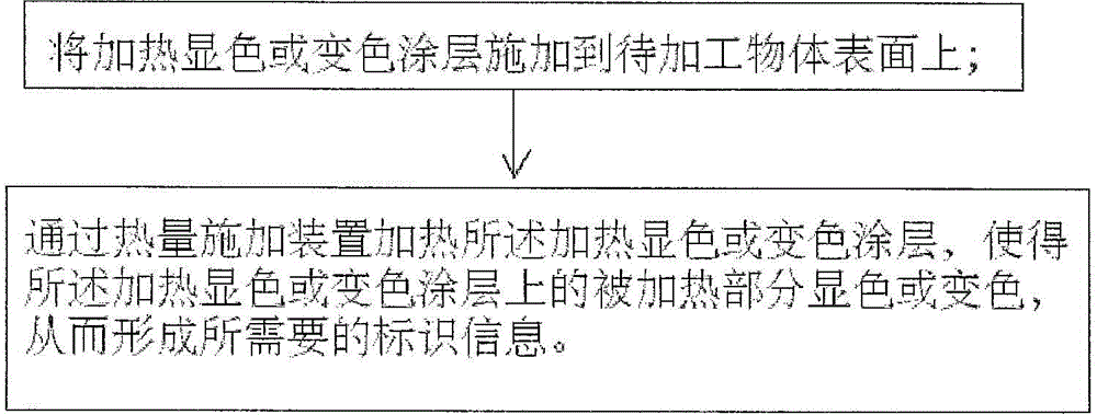
[0090] see figure 1 , which shows a flow chart of a low-power laser fast encoding method according to an embodiment of the present invention.

[0091] Such as figure 1 As shown, the low-power laser fast coding method of the present invention includes the following steps: (1) applying an organic coating to the surface of the object to be processed; and (2) heating the organic coating by a low-power laser application device, so that The heated portion on the ...


PUM


Abstract

The invention provides a low-power laser rapid code endowing method and system. The method comprises the steps that an organic coating developing or changing colors through heating is applied to the surface of a to-be-machined object; and the organic coating is heated through a low-power laser applying device, the heated part on the organic coating develops or changes colors, and accordingly needed identification information is formed. The system comprises a coating applying device and the low-power laser applying device. According to the code endowing method and system, the beneficial effects that an ink-jet printer can read the colors easily and a laser marking machine is large in information amount and high in speed are integrated, and the appearance which is good in attaching force and does not affect marked objects can be formed on various substrates, especially on a low-surface tension substrate.

Description

technical field [0001] The invention relates to the technical field of laser coding or marking, in particular to a low-power laser fast coding method and coding system for forming monochrome or colored identification information on articles or commodities. Background technique [0002] Commodities that are currently sold or circulated in the market, especially fast-moving consumer goods (such as alcohol, beverages, cosmetics, milk powder and other commodities that are closely related to daily consumption), need to mark the production date, batch, etc. on the commodity by assigning a code Identification information. There are two common coding methods: inkjet printer printing and laser marking. [0003] The inkjet printer is an inkjet printing device that is controlled by software and uses a non-contact method to mark on the product. The inkjet printer mainly includes three parts: the ink system, the circuit system, and the nozzle. Inkjet printers can be divided into conti...

Claims


Application Information

Patent Timeline
IPC IPC(8): B41J2/435B41M5/30
Inventor 李旭东李昂
Owner 北京赛腾标识系统股份公司
Features
  • Generate Ideas
  • Intellectual Property
  • Life Sciences
  • Materials
  • Tech Scout
  • Unparalleled Data Quality
  • Higher Quality Content
  • 60% Fewer Hallucinations
Learn More