Manufacturing method for target material assembly

A production method and target technology, which are applied in the production field of target components, can solve the problems of lack of binding performance, inability to obtain binding rate and binding strength of target components, etc.

Inactive Publication Date: 2016-02-17
KONFOONG MATERIALS INTERNATIONAL CO LTD
View PDF8 Cites 6 Cited by
  • Summary
  • Abstract
  • Description
  • Claims
  • Application Information

AI Technical Summary

Problems solved by technology

[0006] However, tungsten-silicon material does not have good bonding perf

Method used


Image

  • Manufacturing method for target material assembly
  • Manufacturing method for target material assembly
  • Manufacturing method for target material assembly

Examples


Embodiment Construction

[0032] As mentioned in the background technology, using the existing welding method, the bonding strength of the tungsten-silicon material directly welded to the back plate is not high, which cannot meet the requirements of the semiconductor target, that is, the tungsten-silicon material with the required bonding rate and bonding strength cannot be obtained. Target components.

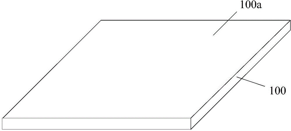
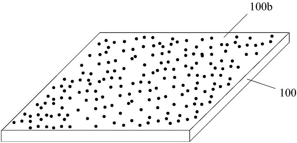
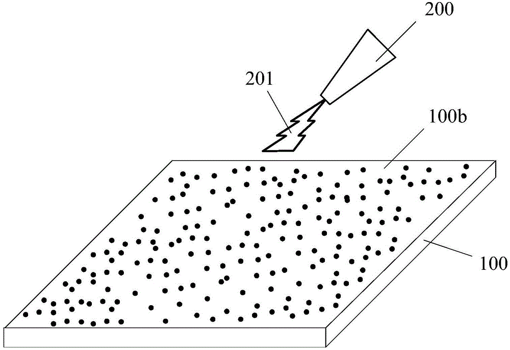
[0033] To this end, the present invention provides a new method for forming a target assembly. The method first provides a tungsten-silicon material target, and then performs sandblasting on the surface of the target to be welded. Afterwards, the target is rinsed, and after the rinse is performed on the target, the surface of the target to be welded is activated. After the activation, an electroless plating process is used on the surface of the target A metal coating is formed on the surface of the target to be welded, and the target and the back plate are welded together by using the metal coating. S...


PUM


Abstract

A manufacturing method for a target material assembly includes the steps of providing a target material which is a tungsten-silicon material, carrying out sand blasting on a to-be-welded surface of the target material, washing the target material after sand blasting, carrying out activating treatment on the to-be-welded surface of the target material after washing, forming a metal coating on the to-be-welded surface of the target material through a chemical plating process after activating treatment, and welding the target material to a back plate together through the metal coating. By means of the manufacturing method for the target material assembly, the target material assembly formed by the tungsten-silicon material has an enough bonding rate and bonding strength.

Description

technical field [0001] The invention relates to the field of semiconductor manufacturing, in particular to a method for manufacturing a target component. Background technique [0002] Generally, the target assembly is composed of a target and a back plate that meet the sputtering performance. The back plate can play a supporting role when the target assembly is assembled to the sputtering base, and can conduct heat. [0003] During the sputtering process, the working environment of the target assembly is relatively harsh, for example, the working temperature of the target assembly is relatively high. Moreover, one side of the target assembly is strongly cooled by cooling water, while the other side is at 10 -9 In the high vacuum environment of Pa, a huge pressure difference is formed on the opposite sides of the target assembly; moreover, the target assembly is in a high-voltage electric field and magnetic field, and will be bombarded by various particles. In such a harsh...

Claims


Application Information

Patent Timeline
IPC IPC(8): C23C14/34
Inventor 姚力军潘杰相原俊夫大岩一彦王学泽张涛
Owner KONFOONG MATERIALS INTERNATIONAL CO LTD
Why Eureka
Try Eureka