Mobile payment apparatus

A mobile payment and driving signal technology, which is applied in the direction of circuit devices, payment system structures, emergency protection circuit devices, etc., can solve the problem of unfavorable POS terminal magnetic head for magnetic pulse signal capture, reduction of effective data range of POS terminals, and restrictions on mobile payment usage scenarios And range and other issues, to achieve the effect of improving power supply stability, achieving maximum power transmission, and widening the time of signal rise

Inactive Publication Date: 2016-02-17
SHANGHAI WEARAPAY INC
View PDF5 Cites 3 Cited by
  • Summary
  • Abstract
  • Description
  • Claims
  • Application Information

AI Technical Summary

Problems solved by technology

[0004] In an embodiment disclosed in the above-mentioned patent application publication number CN104867008A, the mode of directly driving the transmitting coil by the audio port of the smart phone is adopted. In this mode, although the smart phone has sufficient driving ability for the transmitting coil, the It is necessary to use a smart phone to complete the payment behavior when implementing mobile payment. If the user does not carry the smart phone or the power of the smart phone is insufficient, it cannot be implemented, thus limiting the usage scenarios and scope of mobile payment
[0005] In another mobile payment scenario, if the main control chip (micro control unit) is used instead of the smartphone, and the IO port of the main control chip is directly used to drive the transmitting coil, there are the following disadvantages: First, the maximum current flowing through the transmitting coil Limited by the maximum drive capability of the IO port of the main control chip, the magnetic field strength excited by the transmitting coil is limited by the maximum drive current of the IO port, resulting in a reduction in the effective data range of the POS terminal's magnetic head induction and reception, which is not conducive to high efficiency. The performance of the system
Second, when the driving capability is close to the limit of the IO port of the main control chip, it presents a strong inductive load characteristic. When the levels at both ends of the transmitting coil are switched rapidly, a strong spike electrical signal will be formed on the load. After the modulated carrier voltage signal drives the transmitting coil, the magnetic field formed in the space presents sharp rise and fall characteristics, see figure 1 , showing the voltage at both ends of the transmitting coil and the waveform schematic diagram of the magnetic pulse, wherein Vcoil_1 is the voltage waveform at one end of the transmitting coil, Vcoil_2 is the voltage waveform at the other end of the transmitting coil, and Icoil is a schematic diagram of the magnetic pulse signal waveform of the transmitting coil, The peak pulse characteristics of the voltage and magnetic pulse waveform are not conducive to the capture of the magnetic pulse signal by the magnetic head of the POS terminal, which affects the receiving sensitivity

Method used


Image

  • Mobile payment apparatus
  • Mobile payment apparatus
  • Mobile payment apparatus

Examples


Embodiment Construction

[0027] The following will clearly and completely describe the technical solutions in the embodiments of the present invention with reference to the accompanying drawings in the embodiments of the present invention. Obviously, the described embodiments are some of the embodiments of the present invention, but not all of them. Based on the embodiments of the present invention, all other embodiments obtained by persons of ordinary skill in the art without making creative efforts belong to the protection scope of the present invention.

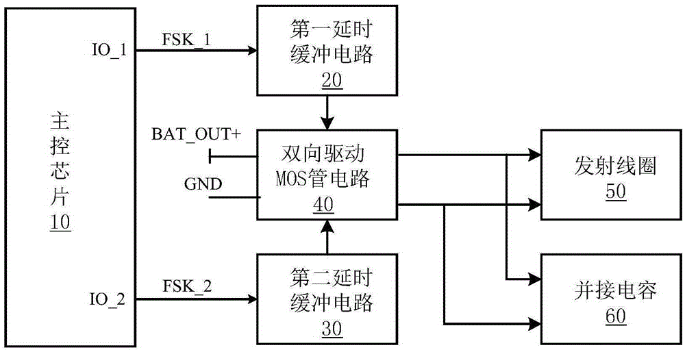
[0028] see figure 1 , shows the functional block diagram of the mobile payment device according to the embodiment of the present invention, which includes: a main control chip 10, which is used to take the account information data as input, and output the two-track data after FSK modulation with the square wave as the basic carrier The FSK signal of information; the first time delay buffer circuit 20, is used for receiving the first FSK signal tha...


PUM


Abstract

The embodiment of the invention discloses a mobile payment apparatus. The mobile payment apparatus comprises a master control chip which is used for receiving account information data as input and outputting FSK signals which take square waves as fundamental carrier waves and carry two-magnetic-track data information after FSK modulation through an IO port; a first time delay buffer circuit which is used for receiving first FSK signals output by a first output port of the master control chip and outputting first driving signals to the first input end of an MOS tube bidirectional driving circuit; a second time delay buffer circuit which is used for receiving second FSK signals output by the second output port of the master control chip and outputting second driving signals to the second input end of the MOS tube bidirectional driving circuit; the MOS tube bidirectional driving circuit which is used for driving an emission coil and has two output ends connected in parallel with the emission coil and a shunt capacitor; and the emission coil which is used for emitting magnetic pulse signals carrying the two-magnetic-track data information to a POS terminal. According to the embodiment of the invention, a termination magnetic head of the POS terminal can capture and identify a pulse magnetic field of the emission coil more conveniently.

Description

technical field [0001] The invention belongs to the field of mobile payment, and in particular relates to a mobile payment device. Background technique [0002] In daily life, users often use mobile applications installed on mobile terminals to complete a certain behavior or achieve a certain effect, for example, use a mobile payment program to perform payment, which is so-called mobile payment. [0003] The application publication number is CN104867008A, and the Chinese patent application 201510289398.X published on August 26, 2015 discloses an offline mobile payment method and system, which can be used to realize non-contact offline payment on POS terminals Same result as paying by card. One of the offline mobile payment systems includes an encoding unit, which is used to input the source data containing the bank card magnetic stripe information to generate a new pulse model matching the source data; a waveform modulation unit, which is used to use the pulse The signal i...

Claims


Application Information

Patent Timeline
Patent Type & Authority Applications(China)
IPC IPC(8): G06Q20/32G06Q20/20H02H9/04
CPCG06K7/00G06Q20/3227G06Q20/204H02H9/044
Inventor 徐雄伟陆水根杨铁党张亦农
Owner SHANGHAI WEARAPAY INC
Why Eureka
Try Eureka