Display panel
A technology for display panels and substrates, applied in the manufacture of electrical components, electrical solid-state devices, semiconductor/solid-state devices, etc., can solve problems such as failure to operate normally
- Summary
- Abstract
- Description
- Claims
- Application Information
AI Technical Summary
Problems solved by technology
Method used
Image
Examples
Embodiment 1
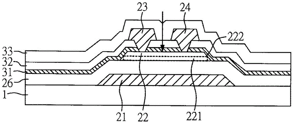
[0016] Please refer to figure 1 , the display panel of the present invention includes: a substrate 1; a thin film transistor unit is arranged on the substrate 1, and the thin film transistor unit includes: a gate electrode 21, a semiconductor layer 22 and an insulating layer 26, wherein the The semiconductor layer 22 includes a carrier channel region 221, and the gate electrode 21 is arranged corresponding to the carrier channel region 221; a first metal oxide layer 32 is arranged on the semiconductor layer 22 and covers the carrier channel region 221 ; and a silicon oxide (SiO x ) or aluminum oxide (Al 2 o 3 ), the isolation layer 31 is disposed between the semiconductor layer 22 and the first metal oxide layer 32, wherein light with a wavelength range between 210nm and 350nm passes through the first metal oxide layer 32 The transmittance is 50% or less.
[0017] In this embodiment, the thin film transistor unit may further include a source electrode 23 and a drain electr...
Embodiment 2
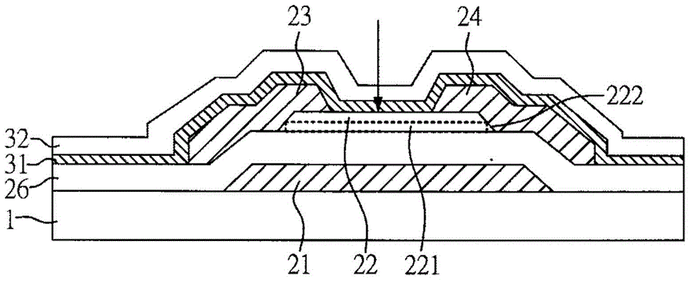
[0026] Please refer to figure 2 , The display panel of another preferred embodiment of the present invention includes: a substrate 1; a thin film transistor unit is arranged on the substrate 1, and the thin film transistor unit includes: a gate electrode 21, a semiconductor layer 22, a Source electrode 23, a drain electrode 24 and an insulating layer 26, wherein the semiconductor layer 22 includes a carrier channel region 221, the carrier channel region 221 is between the source electrode 23 and the drain electrode 24 between, and the gate electrode 21 is set corresponding to the carrier channel region 221; a first metal oxide layer 32 is set on the semiconductor layer 22 and covers the side wall 222 of the semiconductor layer 22, and covers the source pole electrode 23 and the drain electrode 24; and a silicon oxide (SiO x ) or aluminum oxide (Al 2 o 3 ), the isolation layer 31 is disposed between the semiconductor layer 22 and the first metal oxide layer 32, wherein ligh...
Embodiment 3
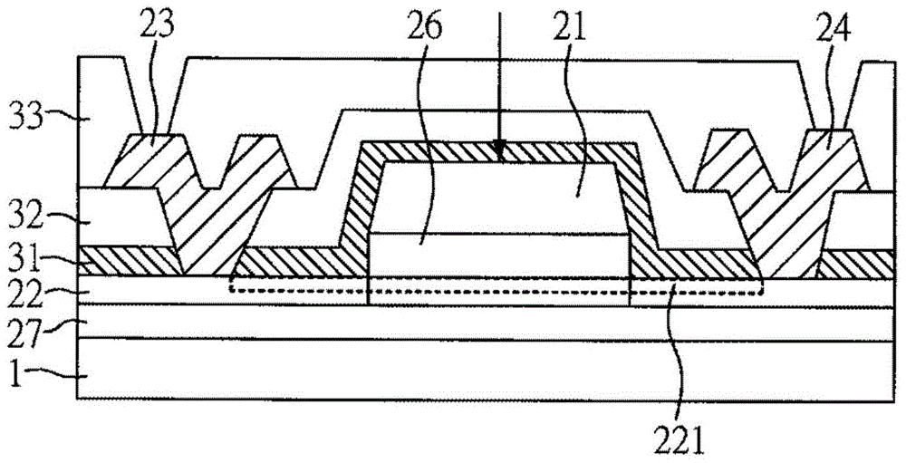
[0031] Please refer to image 3 , The display panel of another preferred embodiment of the present invention includes: a substrate 1; a thin film transistor unit is arranged on the substrate 1, and the thin film transistor unit includes: a gate electrode 21, a semiconductor layer 22, a insulating layer 26 and a buffer layer 27, wherein the semiconductor layer 22 includes a carrier channel region 221, and the gate electrode 21 is arranged above the semiconductor layer 22 and corresponding to the carrier channel region 221; a first metal An oxide layer 32 is disposed on the semiconductor layer 22 and at least covers the carrier channel region 221; and a silicon oxide (SiO x ) or aluminum oxide (Al 2 o 3 ), the isolation layer 31 is disposed between the semiconductor layer 22 and the first metal oxide layer 32, wherein light with a wavelength range between 210nm and 350nm passes through the first metal oxide layer 32 The transmittance is 50% or less.
[0032] In addition, the...
PUM
 Abstract
Description
Claims
Application Information
 - R&D
- Intellectual Property
- Life Sciences
- Materials
- Tech Scout
- Unparalleled Data Quality
- Higher Quality Content
- 60% Fewer Hallucinations
Browse by: Latest US Patents, China's latest patents, Technical Efficacy Thesaurus, Application Domain, Technology Topic, Popular Technical Reports.
© 2025 PatSnap. All rights reserved.Legal|Privacy policy|Modern Slavery Act Transparency Statement|Sitemap|About US| Contact US: help@patsnap.com


