Casting drawing device and drawing method thereof

A technology for casting models and molds, which is applied in the field of casting mold lifters and mold lifters, can solve the problems of time-consuming screw in and out, broken models, and damaged models, so as to reduce production costs, improve production efficiency, Eliminate the effect of mold damage

Inactive Publication Date: 2016-02-24
RONGCHANG JINYI CASTING IND CO LTD
View PDF7 Cites 6 Cited by
  • Summary
  • Abstract
  • Description
  • Claims
  • Application Information

AI Technical Summary

Problems solved by technology

[0004] There are following deficiencies in the above-mentioned two kinds of mold removal methods: 1, the situation that the model slips from the steel drill and damages the mold often occurs when the steel drill is removed from the mold; , Repeatedly knock down on the model, if the casting mold rigidity is low (such as wet mold), the model sinks, which will easily lead to poor dimensional accuracy of the casting; Screw screwing in and out is time-consuming and less efficient

Method used


Image

  • Casting drawing device and drawing method thereof
  • Casting drawing device and drawing method thereof
  • Casting drawing device and drawing method thereof

Examples


Embodiment 1

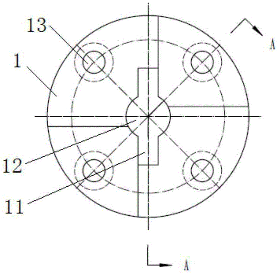
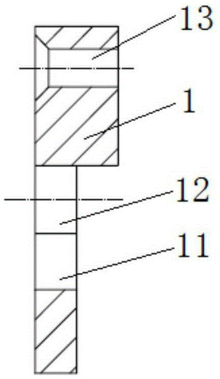
[0030] refer to Figure 1-3 , The casting ejector described in this embodiment includes a fixed plate 1 and an ejector rod.

[0031] The fixed plate 1 is made of medium carbon steel, and has undergone quenching and tempering heat treatment and surface oxidation treatment. The fixed plate 1 has a circular shape as a whole, and is equally divided into four fan-shaped areas as a whole, wherein the thickness of two opposite fan-shaped areas is greater than the thickness of the other two opposite fan-shaped areas. A counterbore 13 is provided near the edge of each fan-shaped area of ​​the fixed plate 1; a through hole 12 is provided in the center of the fixed plate 1, and square grooves 11 are respectively provided on the upper and lower sides of the through hole 12. The outer diameter of the fixed plate is 50mm, 60mm, 65mm or 70mm.

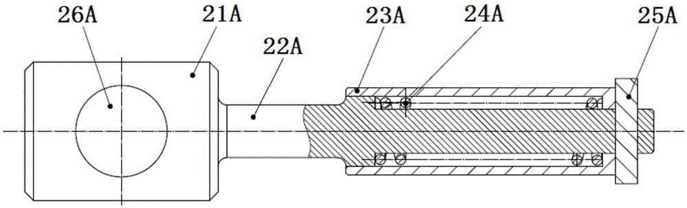
[0032] The ejector lever is a lifting type ejector lever, which includes a rod body 22A, a handle 21A, a sleeve 23A, a spring 24A and a square pin ...

Embodiment 2

[0034] refer to figure 1 , 2 , 4. The casting ejector described in this embodiment includes a fixed plate 1 and an ejector rod.

[0035] The fixed plate 1 is made of medium carbon steel, and has undergone quenching and tempering heat treatment and surface oxidation treatment. The fixed plate 1 has a circular shape as a whole, and is equally divided into four fan-shaped areas as a whole, wherein the thickness of two opposite fan-shaped areas is greater than the thickness of the other two opposite fan-shaped areas. A counterbore 13 is provided near the edge of each fan-shaped area of ​​the fixed plate 1; a through hole 12 is provided in the center of the fixed plate 1, and square grooves 11 are respectively provided on the upper and lower sides of the through hole 12. The outer diameter of the fixed plate is 50mm, 60mm, 65mm or 70mm.

[0036] The ejector lever is a hand-held ejector lever, comprising a rod body 22B, a handle 21B, a sleeve 23B, a spring 24B and a square pin 25...

Embodiment 3

[0058] Ejecting method embodiment 3 (4 fixed plates are installed):

[0059] The present embodiment is to apply the casting mold lifter to the K30 / 150 type air compressor fuselage model. The weight of this model is 65kg. Install the four fixed plates.

[0060] Select the projection point of the center of gravity of the casting model on the parting surface as the origin, and install the fixed plate 1 at four appropriate symmetrical positions. According to the shape of the casting model, the connecting line between the centers of the four fixed plates should be rectangular (square or rectangular) and the fixed plate Install it at an appropriate position symmetrical to the center of gravity of the model, and ensure that the top surface of the fixed plate or the highest point of the top of the fixed countersunk bolt is 0.5-3mm lower than the parting surface of the model.

[0061] Carry out molding in casting mold with foundry model, molding method and step are known in foundry in...


PUM


Abstract

The invention relates to a casting drawing device and a drawing method thereof. The casting drawing device comprises a fixed plate and a drawing rod. The whole fixed plate is round, and a plurality of counter bored holes are evenly formed in the fixed plate. A through hole is formed in the center of the fixed plate, and square grooves are formed in the upper side and the lower side of the through hole respectively. The drawing rod comprises a rod body, a handle, a sleeve, a spring and a square cotter. The handle is arranged at the tail portion of the rod body. The front portion of the rod body is sleeved with the spring. The spring and the rod body are sleeved with the sleeve. The square cotter is located on the front side of the sleeve and mounted at the front end of the rod body in an interference fit mode, and the two ends of the square cotter are symmetrical. The casting drawing device can be rapidly inserted in, locked and retreated in drawing operation, the situation that a casting mold is damaged due to slip of a model can be completely eradicated, and the phenomena that the service life of the model is shortened since steel chisels are knocked into the model, and dimensional accuracy becomes poor since the model is knocked downwards are avoided; thus, the quality and production efficiency are improved, the service life of the mold is prolonged, and the production cost is lowered.

Description

technical field [0001] The invention relates to a casting mold drawing tool and method suitable for different materials such as wooden molds, metal molds, plastic molds, etc., in particular to a casting mold lifting device and a casting method. Background technique [0002] It is one of the basic casting methods to repeatedly use the casting model to make a large number of castings, shape the castings and obtain the required castings, and it still occupies a dominant position in modern industrial production, and mold removal is a necessary process. [0003] There are generally two methods for the existing casting manual modeling: 1. Use steel drills to nail the model, knock the steel drills to loosen the model, then nail the steel drills into the model, and grasp the steel drills to take the model out of the mold ;2. Pre-install the metal plate with screw holes on the model, loosen the mold first when pulling out the mold, then screw the screw into the screw hole, grasp the ...

Claims


Application Information

Patent Timeline
Patent Type & Authority Applications(China)
IPC IPC(8): B22C23/00B22C9/02
CPCB22C23/00B22C9/02
Inventor 何琦
Owner RONGCHANG JINYI CASTING IND CO LTD
Why Eureka
Try Eureka