
Method and vertical flue bottom structure for reducing production of nitrogen oxides by coke oven

A technology of nitrogen oxides and bottom structure, which is used in the heating of coke ovens, coke ovens, and combustible gas heating coke ovens, etc., can solve the problems of high nitrogen oxide emissions, sufficient mixing of circulating exhaust gas, and high combustion temperature in coke ovens. , to achieve the effect of weakening combustion intensity, reducing pollution and reducing combustion temperature

Inactive Publication Date: 2016-02-24
ACRE COKING & REFRACTORY ENG CONSULTING CORP
View PDF4 Cites 6 Cited by
  • Summary
  • Abstract
  • Description
  • Claims
  • Application Information

AI Technical Summary

Problems solved by technology

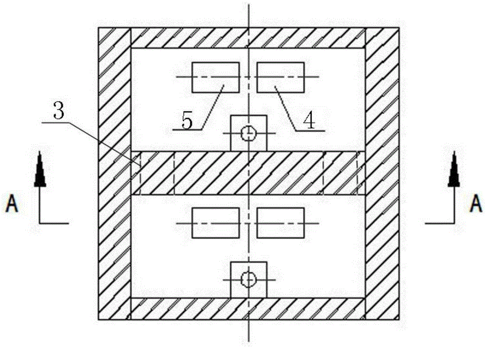
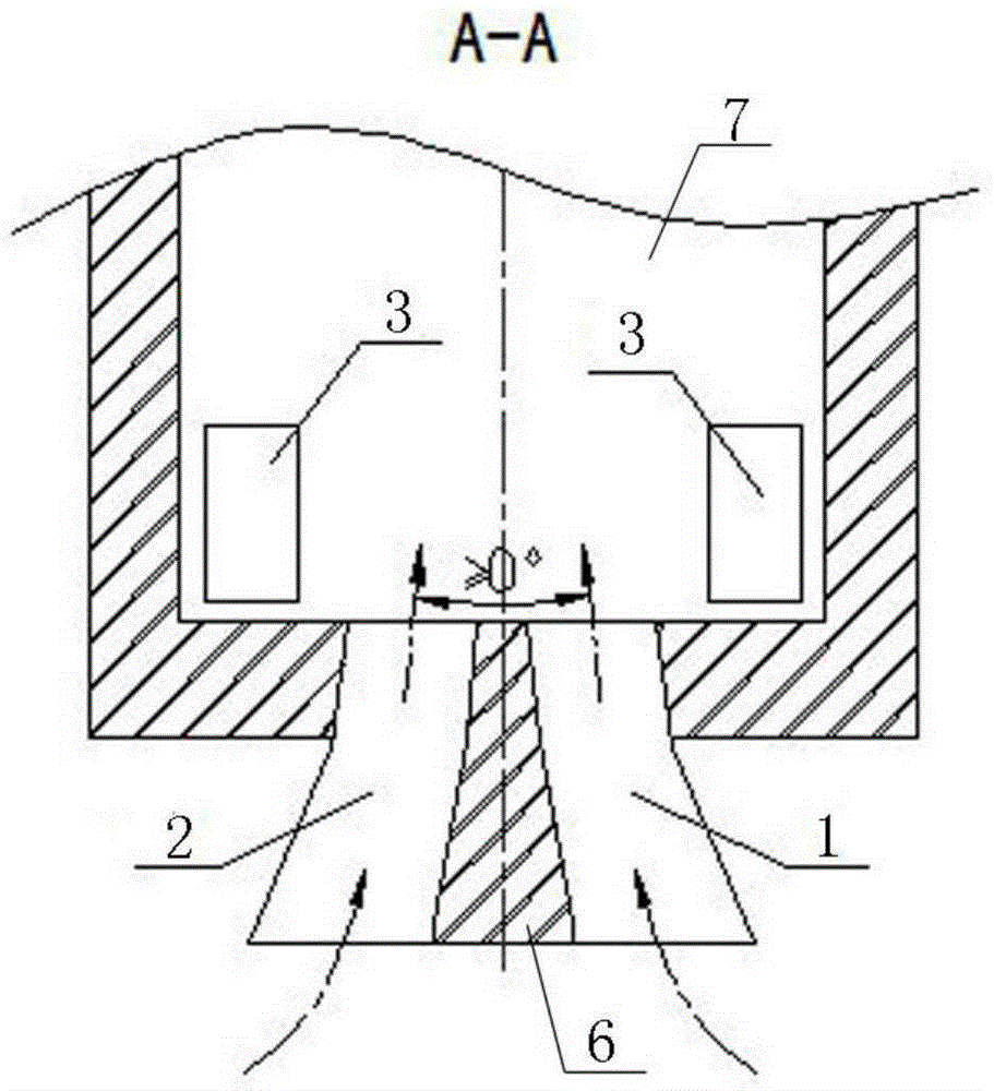
Traditionally designed chute area structure form (as attached figure 2 As shown, the combustible gas inlet 4 and the combustion-supporting gas inlet 5 are arranged perpendicular to the bottom of the fire passage), so that the combustible gas and the combustion-supporting gas flow are sprayed out from the bottom of the fire passage in parallel or opposite to each other, and mixing occurs as soon as the airflow enters the fire passage Combustion, it cannot be fully mixed with the circulating exhaust gas entering from the exhaust gas circulation hole 3 before combustion, so that the combustibles and oxygen participate in the combustion at a relatively high concentration, the combustion is violent, the combustion temperature is high, and a large In the high temperature zone, a large amount of nitrogen oxides is easy to be generated in this zone, making the coke oven nitrogen oxide emissions at a relatively high level

Method used


Image

  • Method and vertical flue bottom structure for reducing production of nitrogen oxides by coke oven
  • Method and vertical flue bottom structure for reducing production of nitrogen oxides by coke oven
  • Method and vertical flue bottom structure for reducing production of nitrogen oxides by coke oven

Examples


Embodiment Construction

[0019] The specific embodiment of the present invention will be further described below in conjunction with accompanying drawing:

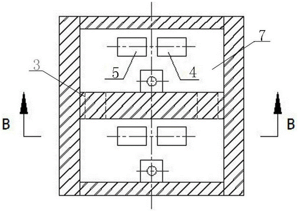
[0020] See Figure 3-Figure 4 , is a structural schematic view of the bottom of the fireway and the chute area of ​​the present invention. A method for reducing the formation of nitrogen oxides in coke ovens according to the present invention, by changing the direction of the combustible gas channel 1 and the combustion-supporting gas channel 2 in the chute area 6, the combustible gas and the combustion-supporting gas respectively enter the standing fire along the direction away from each other. In the channel 7, the combustible gas and combustion-supporting gas are mixed with the circulating waste gas at the bottom of the standing fire channel 7 before burning to reduce the concentration of combustible gas and oxygen, weaken the combustion intensity, and reduce the combustion temperature; the combustible gas and combustion-supporting gas enter th...


PUM

PropertyMeasurementUnit
Lengthaaaaaaaaaa

Abstract

The invention relates to a method and a structure for reducing production of nitrogen oxides by a coke oven. A combustible gas passage in front of a combustible gas inlet and a combustion-supporting gas passage in front of a combustion-supporting gas inlet are respectively arranged obliquely toward the outer sides, and the included angle between the center lines of the two passages is not smaller than 3 degrees. The trends of the combustible gas passage and the combustion-supporting gas passage in a chute area are changed, so that a combustible gas and a combustion-supporting gas respectively enter a vertical flue in opposite directs, are blended with circulation waste gas at the bottom of the vertical flue, and then burn, accordingly, the concentrations of the combustible gas and oxygen are reduced, the combustion intensity is weakened and the combustion temperature is lowered; the blending point of the combustible gas and the combustion-supporting gas which enter the vertical flue is moved upwards, so that the high heating uniformity of the vertical flue is improved, and the production of nitrogen oxides during combustion in the vertical flue is reduced.

Description

technical field [0001] The invention relates to the technical field of coke ovens, in particular to a method capable of reducing the formation of nitrogen oxides in coke ovens and a flue bottom structure. Background technique [0002] When the coke oven is heated, the combustible gas burns at high temperature in the vertical flue, which will produce nitrogen oxides. As pollutant emissions, nitrogen oxides can not only cause environmental problems such as acid rain, photochemical smog, greenhouse effect, and destruction of the ozone layer, but also cause great harm to human health. Studies have shown that the higher the combustion temperature in the coke oven flue, the more nitrogen oxides will be produced. Therefore, during the coke oven heating process, the emission of nitrogen oxides must be strictly controlled. [0003] At present, the methods widely used to control coke oven nitrogen oxide emissions can be divided into two categories: source reduction and end treatment...

Claims


Application Information

Patent Timeline
IPC IPC(8): C10B21/10C10B21/18
Inventor 康婷王明登王满李振国徐妍景殿策
Owner ACRE COKING & REFRACTORY ENG CONSULTING CORP
Learn More