Traffic signal lamp optical system realized by laser light source and diffractive optical elements

A diffractive optical element and traffic signal light technology, applied in the field of optoelectronic communication, can solve the problems of high application environment requirements, limited product market application, inability to realize lighting light field, etc., to achieve low cost, improved function and applicability, light beam The effect of controllable propagation direction

Inactive Publication Date: 2016-03-02
JIAXING UPHOTON OPTOELECTRONICS TECH CO LTD
View PDF5 Cites 9 Cited by
  • Summary
  • Abstract
  • Description
  • Claims
  • Application Information

AI Technical Summary

Problems solved by technology

The traditional design method is to modulate the incident light field by means of refraction, occlusion, and imaging. The design method has complex optical elements, a large number, very low light utilization efficiency, and single function, which cannot realize complex lighting light fields. For example, for new application fields such as traffic lights with large inclination angles, asymmetric correction of light intensity distribution, and long-distance traffic lights over 100 meters, traditional design methods cannot be realized.
At the same time, the traditional lighting light field design method has large optical devices, high cost, and high requirements for the application environment. Fine dust on the surface of the optical device will cause serious defects in the special-shaped light field. The above factors have caused many problems for the use of this product. Unfavorable factors seriously limit the market application of the product
[0003] In modern technology, with the application development of the market, accessory products and corresponding optoelectronic equipment and systems, the application of optoelectronic products in the accessory application market is becoming more and more extensive, and the requirements for technical indicators of optoelectronic products are also getting higher and higher. The application market of laser traffic signal lighting light fields with special patterns designed for demand is developing rapidly, such as high-definition laser traffic signal products, laser traffic signal light products with special patterns, etc. The development of products in these fields poses complex requirements for active lighting light fields. , demanding requirements, the traditional lighting optical system has a complex optical system, large size, high cost, and complicated adjustment, which requires the movement and joint adjustment of multiple lenses, and the light field control method is simple, which cannot realize complex and changeable lighting. The light field distribution can no longer meet the needs of the application field. Based on the development of diffractive optics and laser technology, it has provided a technical basis for the realization of special lighting laser light fields. The diffractive optical element is a new type of optical element that has only recently matured. Its design principle It is essentially different from traditional refractive optics. It is based on the wavefront phase characteristics of the light field for light field modulation design. It belongs to wavelength-level nano-micro-optical devices. In the light field area of ​​​​1 mm, it can achieve hundreds of millions of The advanced light field control unit can make rich and flexible adjustments to the input light field, and can almost meet the requirements of any complex output light field. It is small in size, powerful in function, and highly efficient in light intensity utilization. It is the future laser traffic signal field. important application technology

Method used


Image

  • Traffic signal lamp optical system realized by laser light source and diffractive optical elements
  • Traffic signal lamp optical system realized by laser light source and diffractive optical elements
  • Traffic signal lamp optical system realized by laser light source and diffractive optical elements

Examples


Embodiment Construction

[0025] The present invention will be described in further detail below in conjunction with the accompanying drawings, but it is not intended to limit the protection scope of the present invention.

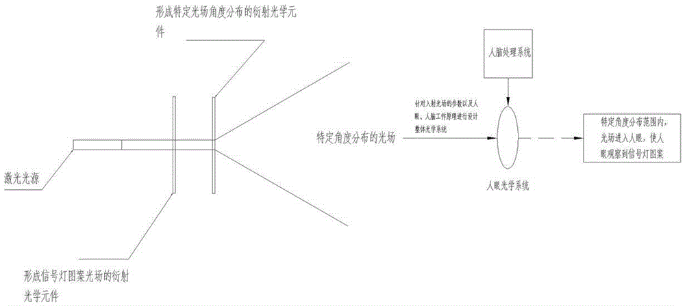
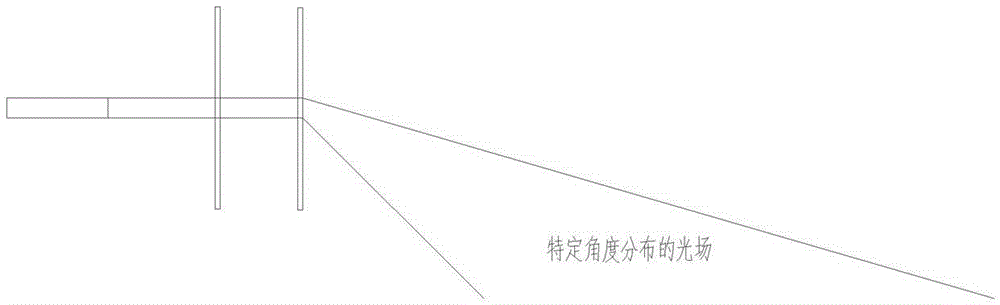
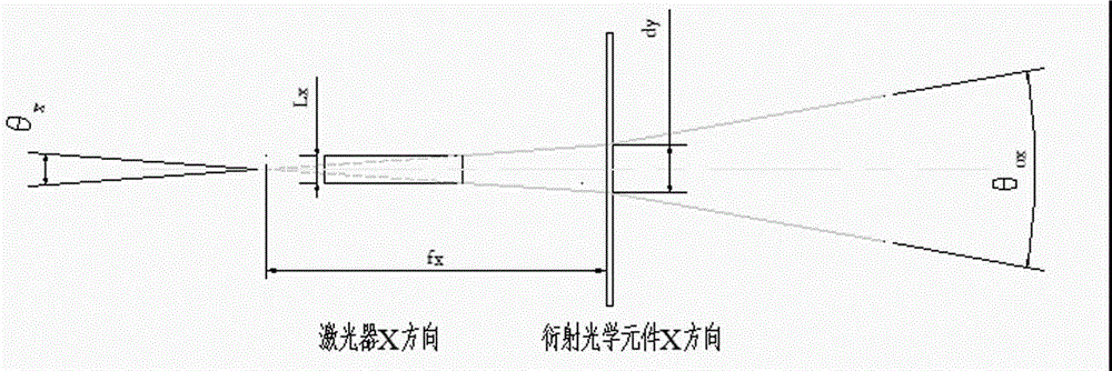
[0026] Such as figure 1 As shown, the design scheme of the first diffractive optical element is: the incident light beam is a parallel or divergent laser beam, and the surface of the diffractive optical element has microscopic concave-convex topography on the order of nanometers, and the microscopic concave-convex topography is based on the incident light beam The optical parameters and the optical parameters of the required outgoing light field are designed, and the wavefront of the incident beam is phase-modulated through the concave-convex shape, and the diffraction and interference characteristics of the incident beam passing through the diffractive optical element are realized. The desired outgoing light field. The diffractive optical element is designed according to the opti...


PUM


Abstract

The invention discloses a traffic signal lamp optical system realized by a laser light source and diffractive optical elements. The traffic signal lamp optical system includes a laser radiation light source, a first diffractive optical element and a second diffractive optical element; after a laser light field irradiates the first diffractive optical element, the first diffractive optical element realizes light field distribution of a laser signal lamp pattern shape; and the light field irradiates the second diffractive optical element; after being subjected to the optical modulation of the second diffractive optical element, the light field of the laser signal lamp pattern shape is transmitted along a specific angle region. With the traffic signal lamp optical system of the invention adopted, the signal lamp light emitting body realized by the laser radiation light source and the diffractive optical elements only can be seen by eyes in an angle region required by ''traffic signal lamp light field space angle distribution standard'', and light energy is not transmitted at the other regions, and the signal lamp light emitting body cannot be observed; light field energy is effectively utilized, and energy can be saved; and invalid light field distribution of all regions except a region specified by the ''standard'' can be eliminated thoroughly, and light pollution of signal lamps can be eliminated.

Description

technical field [0001] The invention belongs to the field of photoelectric communication, in particular to a traffic signal light optical system realized by laser light sources and diffractive optical elements. Background technique [0002] The optical design of the traditional traffic signal light field is based on the characteristics of the light source (such as halogen lamps, etc.), by using refractive optical elements, such as lenses, reflectors, microlens arrays, lenses, and astigmatism sheets, to realize the optical design of the light field. Secondary modulation to achieve the output of the required light field. The traditional design method is to modulate the incident light field by means of refraction, occlusion, and imaging. The design method has complex optical elements, a large number, very low light utilization efficiency, and single function, which cannot realize complex lighting light fields. For example, for new application areas such as traffic lights with ...

Claims


Application Information

Patent Timeline
Patent Type & Authority Applications(China)
IPC IPC(8): G02B27/42G08G1/095
CPCG02B27/4233G08G1/095
Inventor 贲宇尹晓东田克汉霍轶杰
Owner JIAXING UPHOTON OPTOELECTRONICS TECH CO LTD
Why Eureka
Try Eureka