

Smashing equipment for smashing of glass fiber composite material or rubber material
A composite material and rubber material technology, applied in the field of processing equipment, can solve the problems of recycling limitation, powder glass fiber length, etc., and achieve the effects of stable pulverized material index, high pulverization efficiency, and adjustable particle size
- Summary
- Abstract
- Description
- Claims
- Application Information
AI Technical Summary
Problems solved by technology
Method used
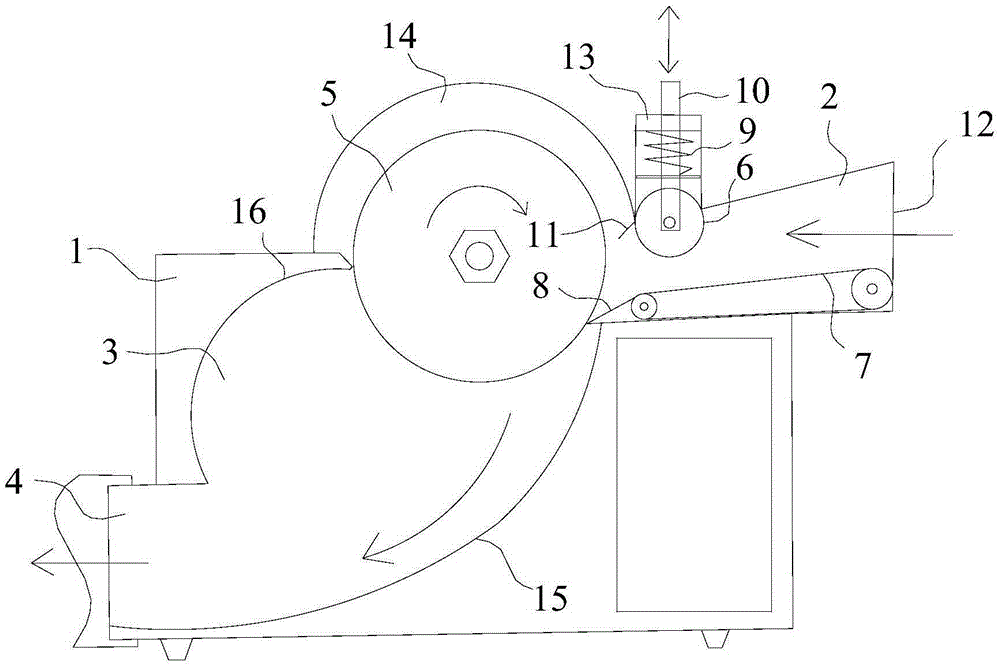
Image

Examples
Embodiment 1
[0073] Embodiment 1 (laboratory model)
[0074] The cutting knife adopts diamond corrugated slices and diamond thickened slotted slices to be superimposed and combined. The slice gap is separated by a 4mm barrier gasket. The slice knife edge (referring to the gap between the outer edges of two adjacent slices) is 0.5mm--1mm , using 5+4 nine slices to form a cutting mechanism with an arrangement width of about 70mm.
[0075] The nine slices correspond to A-D-A-D-A-D-A-D-A in Table 1 in turn.
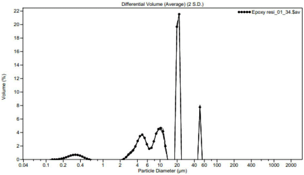
[0076] When in use, the pre-cut material is decomposed into blocks or strips with a cross-sectional width of less than 70mm*60mm, and then cut. After cutting, it is sieved with 120 meshes, and the mesh passing rate is >85%. See the particle size distribution after passing through the screen figure 2 , the cutting efficiency is shown in Table 2.
Embodiment 2
[0077] Embodiment 2 (industrial minicomputer)
[0078] The cutting knife is superimposed and combined with diamond corrugated slices and diamond thickened slotted slices. The slice gap is isolated by a 6mm barrier gasket. The gap between the slice blades is 0.5mm--1mm. 5+4 nine slices are composed of an arrangement width of about 100mm. cutting mechanism.
[0079] The nine slices correspond to B-E-B-E-B-E-B-E-B in Table 1 in turn.
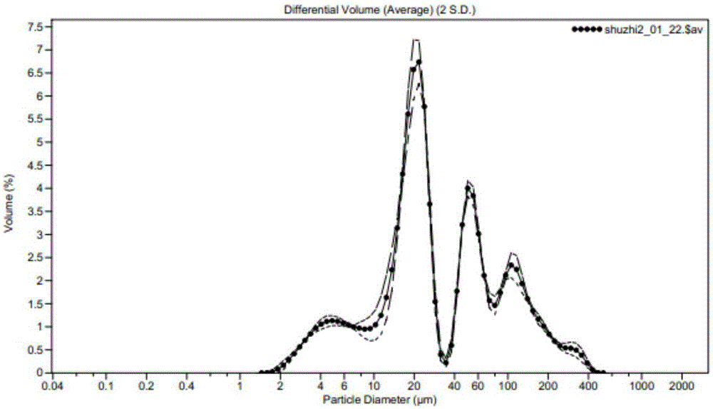
[0080] When used, the pre-cut material is decomposed into block or strip materials with a cross-sectional width less than 100mm*60mm, and then cut. The particle size distribution after cutting is shown in image 3 , the cutting efficiency is shown in Table 2.
Embodiment 3
[0081] Embodiment 3 (industrial mainframe)
[0082] The cutting knife adopts V-diameter diamond grooved slices and diamond thickened grooved slices to be superimposed and combined. The slice gap is separated by a 6mm barrier gasket. The gap between the slice blades is 1mm--2mm, and the arrangement width of 5+4 nine slices is 150mm. Left and right cutting mechanism.
[0083] The nine slices correspond to C-F-C-F-C-F-C-F-C in Table 1 in turn.
[0084] When using, decompose the pre-cut material into block or strip materials with a cross-sectional width less than 150mm*60mm, and then cut them. See the particle size distribution after cutting. Figure 4 , the cutting efficiency is shown in Table 2.
[0085] Performance Characterization
[0086] The pulverization efficiency is the output of the powder obtained from the continuous production of the pulverization equipment of the corresponding model of the present invention for 1 hour, and is marked in kilograms per hour; the parti...
PUM
| Property | Measurement | Unit |
|---|---|---|
| particle size | aaaaa | aaaaa |
| thickness | aaaaa | aaaaa |
| particle diameter | aaaaa | aaaaa |
Abstract
Description
Claims
Application Information