
Giant Magnetostrictive Rotary Ultrasonic Vibration Tool Holder

A technology of giant magnetostriction and giant magnetostrictive rods, which is applied in the direction of vibrating fluid, stone processing tools, stone processing equipment, etc., can solve the temperature rise of giant magnetostrictive ultrasonic transducers and affect the stability of output amplitude Safety and other issues, to achieve the effect of large output power, high magnetostriction coefficient, and high energy density

Active Publication Date: 2017-03-08
TSINGHUA UNIV
View PDF7 Cites 2 Cited by
  • Summary
  • Abstract
  • Description
  • Claims
  • Application Information

AI Technical Summary

Problems solved by technology

[0005] 1. In a high-frequency alternating electromagnetic field, energy dissipation such as eddy current loss, hysteresis loss, and mechanical loss causes a significant temperature rise in the giant magnetostrictive ultrasonic transducer, which seriously affects the stability of the output amplitude and the safety of long-term work sex

Method used


Image

  • Giant Magnetostrictive Rotary Ultrasonic Vibration Tool Holder
  • Giant Magnetostrictive Rotary Ultrasonic Vibration Tool Holder
  • Giant Magnetostrictive Rotary Ultrasonic Vibration Tool Holder

Examples


Embodiment Construction

[0024] In order to achieve the above purpose, a giant magnetostrictive rotary ultrasonic vibration tool holder provided by the present invention is described as follows in conjunction with the accompanying drawings and embodiments:

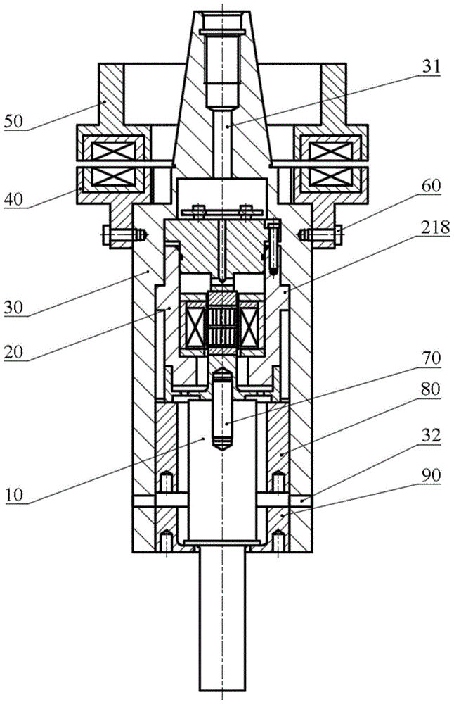
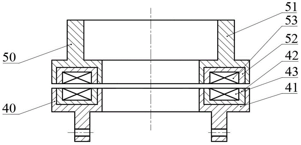
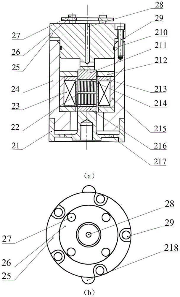
[0025] The embodiment structure of a giant magnetostrictive rotary ultrasonic vibration tool holder proposed by the present invention is as follows: figure 1 As shown, the structure is suitable for cooling by an air-cooling system, including a horn 10, a giant magnetostrictive ultrasonic transducer 20, a casing 24, a hollow handle 30 (with a central hole 31 in the handle, and an air hole 32 in the handle. ), a non-contact power transmission system made up of secondary side parts 40 and primary side parts 50, screws 60, screw rods 70, threaded pressing blocks 80 and 90; the connection and matching relationship of each part is: giant magnetostrictive ultrasonic transducer 20 is connected with the horn 10 through the screw rod 70 to form an integral ...


PUM


Abstract

The invention relates to a giant magnetostrictive rotary ultrasonic vibration knife handle and belongs to the technical field of ultrasonic precise special machining. The knife handle comprises an amplitude-change pole, a giant magnetostrictive ultrasonic transducer, a hollow knife handle body, an auxiliary side component, a primary side component and a threaded pressing block, wherein the giant magnetostrictive ultrasonic transducer is connected with the amplitude-change pole through a threaded rod and installed in a cavity in the lower portion of the knife handle body; an ultrasonic vibrator formed by connecting the giant magnetostrictive ultrasonic transducer with the amplitude-change pole makes contact with the inner wall of the knife handle body, the lower end of the giant magnetostrictive ultrasonic transducer is tightly pressed onto the knife handle body through the threaded pressing block, and the threaded pressing block is connected with the knife handle body through threads; the lower end of the amplitude-change pole is tightly pressed through the threaded pressing block, and the threaded pressing block is connected with the knife handle body; the lower end of the auxiliary side component is fixed to the knife handle body through a screw, and the primary side component is fixed to the end face of a machine tool spindle. According to the giant magnetostrictive rotary ultrasonic vibration knife handle, the problem of heating of the transducer is effectively solved by means of a giant magnetostrictive material of a slice structure and an air cooling system. By the adoption of the knife handle, the machining efficiency can be improved. In addition, the knife handle can be suitable for any knife handle connection standards.

Description

technical field [0001] The invention belongs to the technical field of ultrasonic precision special processing, in particular to a rotating ultrasonic vibration tool holder based on giant magnetostrictive material (GMM). Background technique [0002] In the high-speed cutting of hard and brittle materials, the tool head rotates at high speed while adding ultrasonic mechanical vibration, which can reduce the cutting force, improve the processing quality and prolong the tool life. Relevant studies have shown that: within a certain range, increasing the ultrasonic power and increasing the ultrasonic amplitude can further reduce the cutting force and improve the processing efficiency. Therefore, the design of high-power rotary ultrasonic machining system has become the development trend of ultrasonic equipment. [0003] The ultrasonic tool holder is the core component of the rotary ultrasonic machining system. At present, there are two kinds of ultrasonic transducer materials c...

Claims


Application Information

Patent Timeline
Patent Type & Authority Patents(China)
IPC IPC(8): B28D1/00B06B1/08
CPCB06B1/08B28D1/00
Inventor 张建富冯平法蔡万宠吴志军郁鼎文
Owner TSINGHUA UNIV
Learn More