Backwashable horizontal underflow artificial wetland capable of retarding front section clogging reducing

A technology of horizontal subsurface flow and constructed wetland, applied in sustainable biological treatment, biological water/sewage treatment, water/sludge/sewage treatment, etc. Load blockage and other problems, to achieve the effect of large particle size, convenient backwashing, and reducing hydraulic loss

Inactive Publication Date: 2016-03-16
CHINA UNIV OF MINING & TECH
View PDF8 Cites 3 Cited by
  • Summary
  • Abstract
  • Description
  • Claims
  • Application Information

AI Technical Summary

Problems solved by technology

The Shenzhen Bainikeng Yantian Constructed Wetland built in 1990 in my country also caused serious blockage due to insufficient pretreatment and excessive hydraulic load, which seriously affected the purification effect.
[0004] For horizontal subsurface flow constructed wetlands, the blockage mainly occurs at the front end. At present, the most commonly used method to solve the blockage of constructed wetlands is to stop and rotate crops. Although this method has a good effect and can restore a certain porosity, there are two obvious shortcomings. One is Stopping and rotating crops requires other wetlands to replace them to process sewage, which will increase the area occupied and construction costs; second, this method can only solve the blockage caused by biological factors, but cannot solve the blockage caused by inorganic substances

Method used


Image

  • Backwashable horizontal underflow artificial wetland capable of retarding front section clogging reducing
  • Backwashable horizontal underflow artificial wetland capable of retarding front section clogging reducing
  • Backwashable horizontal underflow artificial wetland capable of retarding front section clogging reducing

Examples


Embodiment Construction

[0017] The present invention will be further described below in conjunction with the accompanying drawings.

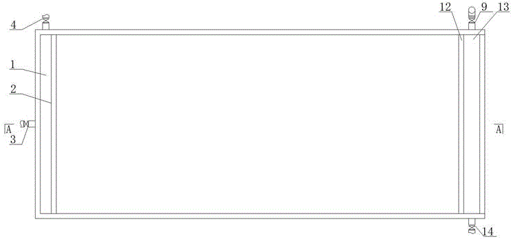
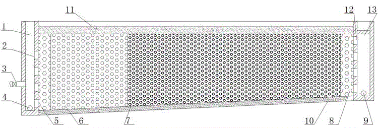
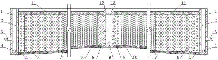
[0018] Method 1: if figure 1 and figure 2 As shown, it is an implementation of the present invention: same as the conventional constructed wetland, it has a large particle size uniform water distribution area 5, a large particle size uniform water collection area 8, an adjustable water level water outlet device 9, an anti-seepage layer 10 and surface soil 11. The first 1 / 3 section of the wetland is filled with matrix with a particle size of 16 mm to 25 mm, and the rear section is filled with matrix with a particle size of 4 mm to 8 mm. The top of the outlet channel 13 is sealed and the slope at the bottom is 0.5%.

[0019] When treating sewage in the wetland, it is necessary to close the backwash outlet valve 4 and the backwash valve 14, and the sewage enters the wetland matrix through the water inlet valve 3, the water inlet channel 1 and the water inlet perforated...


PUM

PropertyMeasurementUnit
particle diameteraaaaaaaaaa

Abstract

The invention relates to a backwashable horizontal underflow artificial wetland capable of retarding front section clogging. The backwashable horizontal underflow artificial wetland is characterized in that the top portion of a water outlet ditch is sealed, the particle size of the wetland front section (front 1 / 4-1 / 2) matrix is larger than the particle size of the rear section matrix, the bottom portion from the water inlet end to the water outlet end has rising slope, the water inflow and the water outflow use perforated walls, the length is less than the conventional artificial common length and is generally less than 15 m, the maximum length does not exceed 20 mm, the particle size of the front section matrix is 12-30 mm, the particle size of the rear section matrix is 4-12 mm, the rising slope from the water inlet end to the water outlet end is 0.5-2%, and the holes on the water inlet perforated wall and the water outlet perforated wall are uniformly arranged in the horizontal direction and in the vertical direction. According to the present invention, the particle size of the front end is larger than the particle size of the rear section so as to retard the wetland front end clogging and improve the hydraulic efficiency of the wetland, the sufficient pressure can be provided through the water outlet ditch sealing, and the wetland clogging is solved through the backwashing.

Description

technical field [0001] The invention relates to the technical field of sewage treatment, in particular to a backwashable horizontal underflow artificial wetland capable of slowing down front-stage blockage. Background technique [0002] Constructed wetland is a new wastewater biological treatment technology developed in the 1970s. It has the characteristics of low investment, low energy consumption, good effluent quality, strong nitrogen and phosphorus removal functions, and convenient operation and management. It has been accepted by countries all over the world and used to treat various forms of wastewater. According to the investigation by the U.S. Environmental Protection Agency (USEPA), as of 2000, there were more than 600 constructed wetland projects in the United States for the treatment of municipal, industrial and agricultural wastewater, and at least 200 constructed wetlands in Denmark, Germany, Britain and other EU member countries (most of them are Subsurface we...

Claims


Application Information

Patent Timeline
Patent Type & Authority Applications(China)
IPC IPC(8): C02F3/32
CPCY02W10/10
Inventor 湛含辉王良杰刘彤
Owner CHINA UNIV OF MINING & TECH
Why Eureka
Try Eureka