
A kind of gas-filled stirring cyanidation leaching gold extraction tank and its application

A technology of aeration stirring and cyanidation leaching, which is applied in the direction of improving process efficiency, can solve the problems of insufficient stirring and other problems, and achieve the effects of fast start-up speed, improved contact time, and sufficient oxygenation

Active Publication Date: 2017-12-26
GANSU ZHAOJIN PRECIOUS METALS SMELTING
View PDF7 Cites 0 Cited by
  • Summary
  • Abstract
  • Description
  • Claims
  • Application Information

AI Technical Summary

Problems solved by technology

Although the device can stir through the air, but the stirring is not sufficient, it is still necessary to stir the main engine to drive the double impeller to rotate to assist in stirring the pulp

Method used


Image

  • A kind of gas-filled stirring cyanidation leaching gold extraction tank and its application
  • A kind of gas-filled stirring cyanidation leaching gold extraction tank and its application

Examples


Embodiment 1

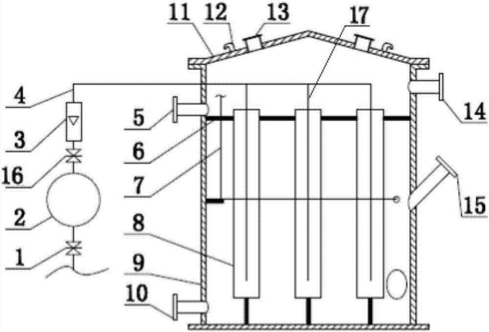
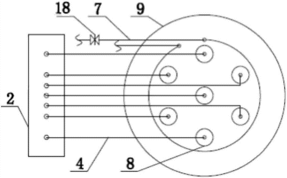
[0031] Such as Figure 1-2 Shown.

[0032] A gas-filled stirring cyanide leaching gold extraction tank includes a carbon steel tank body 9, a carbon steel tank cover 11, a HVAC pipe 7 and seven slurry diversion cylinders 8; the slurry diversion cylinder 8 is vertically arranged on the carbon steel tank body 9; The slurry guide tube 8 is provided with an inflatable stirring tube 17; the HVAC tube 7 is arranged around the side wall of the carbon steel tank 9. When the gas-filled stirring cyanide leaching gold extraction tank of the present invention is in use, compressed air is input into the gas-filled stirring pipe 17 through a compressor, and while oxygen is being filled, it plays a role of stirring. Arranging the aerated stirring tube 17 in the slurry guide tube 8 prevents the aerated stirring tube 17 from directly contacting the slurry, and prevents the slurry from entering the aerated stirring tube 17 and causing a plugging of the tube. Another advantage of this structure i...

Embodiment 2

[0034] The gas-filled stirring cyanide leaching gold extraction tank described in Example 1, the difference is that the carbon steel tank body 9 is a cylindrical carbon steel tank body with a height-to-diameter ratio of 2; the slurry guide tube 8 is made of carbon steel , The diameter is 500mm; the diameter of the aerated stirring tube 17 is 30mm; the distance between the slurry guide tube 8 and the bottom of the carbon steel tank 9 is 1000mm. The slurry mixing effect is the best within this distance and the slurry dispersion is better.

Embodiment 3

[0036] The gas-filled stirred cyanide leaching gold extraction tank as described in Example 1, the difference is that the HVAC pipe 7 has a diameter of 50 mm, and a third flow regulating valve 18 is provided at the inlet of the HVAC pipe 7. The flow regulating valve is used to control the flow of hot water into the HVAC pipe 7, which heats the slurry in the cold climate in winter to stabilize the reaction temperature.


PUM

PropertyMeasurementUnit
diameteraaaaaaaaaa
diameteraaaaaaaaaa
diameteraaaaaaaaaa

Abstract

The invention relates to an air agitation cyanidation leaching gold extraction tank and application. The air agitation cyanidation leaching gold extraction tank comprises a carbon steel tank body, a carbon steel tank cover, a heating and ventilation pipe and a plurality of ore pulp guide shells, wherein the ore pulp guide shells are vertically arranged in the carbon steel tank body; air agitation pipes are arranged in the ore pulp guide shells; the heating and ventilation pipe is arranged on the side wall of the carbon steel tank body in a surrounding manner. When the air agitation cyanidation leaching gold extraction tank disclosed by the invention is used, compressed air is input into the air agitation pipes through a compressor, oxygen is charged, and besides, the effect of agitation is achieved. The air agitation pipes are arranged in the ore pulp guide shells, so that the situation that the air agitation pipes are in direct contact with ore pulp is avoided, and the ore pulp is prevented from entering the air agitation pipes.

Description

Technical field [0001] The invention relates to a gas-filled stirring cyanide leaching gold extraction tank and its application, and belongs to the technical field of non-ferrous metallurgy extraction. technical background [0002] In the cyanidation gold extraction process, the cyanidation leaching of gold requires oxygen to participate in the reaction. Therefore, the cyanidation leaching gold extraction process needs to continuously blow air into the stirred leaching tank while stirring. At present, cyanide leaching equipment mainly adopts mechanical stirring leaching tank plus an air blowing device to supplement air in the leaching tank and an air-floating aerodynamic leaching tank. The mechanical agitation leaching tank with an additional aeration device has the disadvantages of complex rotating structure, high failure rate, high maintenance cost, high energy consumption, and low gold leaching rate. The air-floating aerodynamic leaching tank has no mechanical operating parts...

Claims


Application Information

Patent Timeline
Patent Type & Authority Patents(China)
IPC IPC(8): C22B11/08C22B3/02
CPCC22B3/02C22B11/04C22B11/08Y02P10/20
Inventor 刘朋路良山杨斌喜王福鑫刘文君
Owner GANSU ZHAOJIN PRECIOUS METALS SMELTING
Learn More