Two-electrode gas switch

A gas switch and electrode technology, applied in the pulse field, can solve problems such as short service life, and achieve the effect of improving service life, avoiding influence and prolonging life.

Active Publication Date: 2017-09-08
XJ POWER CO LTD +3
View PDF4 Cites 0 Cited by
  • Summary
  • Abstract
  • Description
  • Claims
  • Application Information

AI Technical Summary

Problems solved by technology

[0004] The purpose of the present invention is to provide a two-electrode gas switch to solve the problem of short service life of the existing two-electrode gas switch due to electrode ablation and graphite particle splashing

Method used


Image

  • Two-electrode gas switch
  • Two-electrode gas switch
  • Two-electrode gas switch

Examples


Embodiment Construction

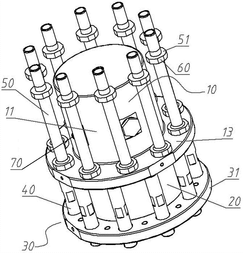
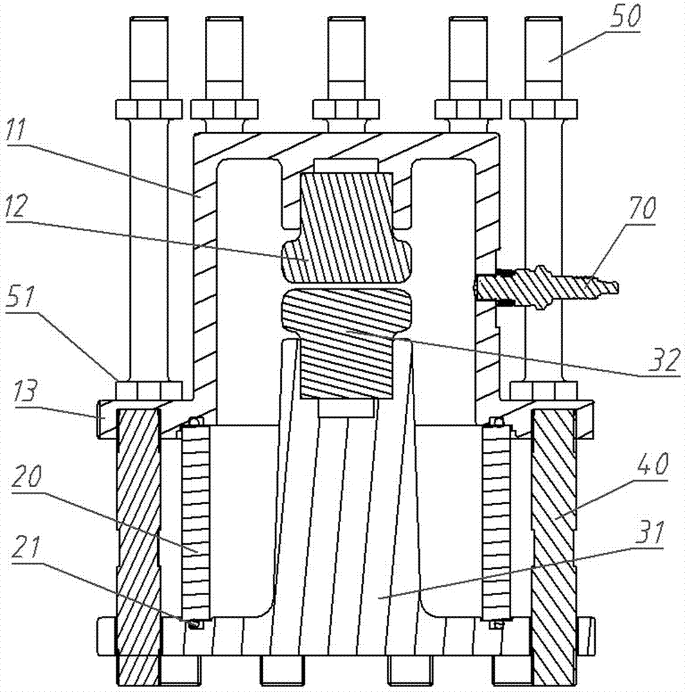
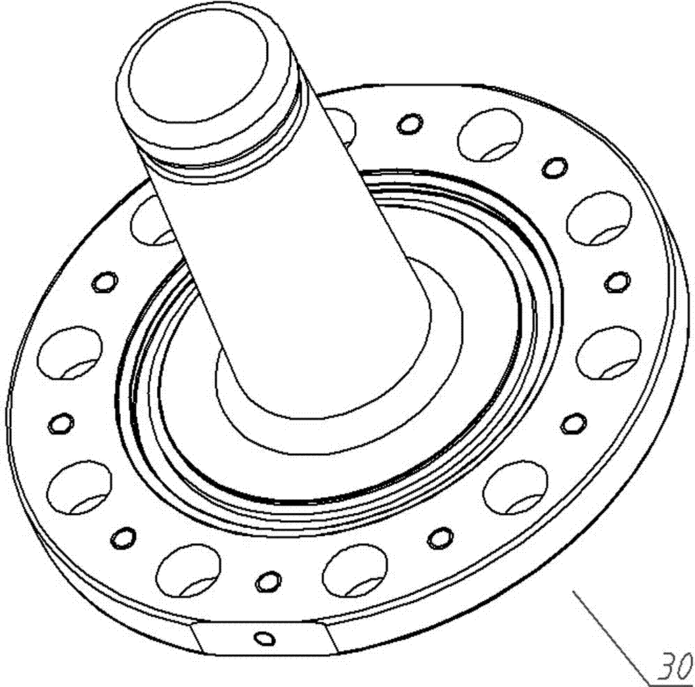
[0023] An embodiment of the two-electrode gas switch of the present invention is figure 1 As shown in Figure 7, it is a coaxial reflow two-electrode gas spark switch, which is mainly composed of 5 parts: an upper cover assembly 10, an insulating cylinder 20, a base assembly 30, an insulating pull rod 40 and a conductive column 50. The upper cover assembly 10 includes a first electrode seat 11 and a first electrode 12 , and the base assembly 30 includes a second electrode seat 31 and a second electrode 32 . The first electrode seat 11 is barrel-shaped with radial side walls, an upward bottom wall and a downward opening, and the second electrode seat 31 is an upside-down T-shape as a whole.

[0024] Both the base assembly 30 and the upper cover assembly 10 are made of 45# steel to ensure the structural strength, and at the same time improve the electric corrosion resistance of the flange joints of the base assembly 30 and the upper cover assembly 10 under high power pulse curren...


PUM


Abstract

The invention relates to a two-electrode gas switch. The two-electrode gas switch comprises a first electrode base, a second electrode base, and two electrodes which are used for forming electrode gaps. The first electrode base is tubular. The electrode gaps are arranged in the internal cavity of the first electrode base. The radial side wall of the first electrode base is provided with a conductive connection structure which is used for enabling the first electrode base to be conductively connected with an external object. The conductive connection structure is arranged at one side, which is close to the second electrode base, of the electrode gaps in the axial direction of the first electrode base. The direction of current flowing through the radial side wall of the first electrode base is opposite to the direction of current flowing through the electrode gaps when current flows. The electromagnetic force generated by current flowing through the radial side wall of the first electrode base affects on the discharge arcs of the two electrode gaps to generate hooping constraint force on the discharge arcs of the two electrode gaps so that heat, the arcs and graphite particles are enabled to be concentrated, more graphite particles are enabled to be oxidized into gas, pollution of the graphite particles to insulating cylinders can be reduced and the service life of the switch can be prolonged.

Description

technical field [0001] The invention relates to pulse technology, in particular to a two-electrode gas switch. Background technique [0002] In the ultra-high power solid-state laser system, the energy subsystem mainly provides large-capacity, high-voltage pulse energy pumping for the laser optical driver. The energy subsystem is composed of a large number of energy modules and control systems. The main function of the energy module is to use high-voltage energy storage. By triggering the high-voltage discharge switch to conduct, the output power pulse energy is pumped. The voltage level of energy modules generally ranges from a dozen kV to more than 20 kV, and the energy released by a single power pulse ranges from tens of kJ to several MJ. Therefore, in high-voltage and high-power pulse energy modules, the high-voltage discharge switch plays a vital role. effect. The high-voltage discharge switch requires a flow capacity of several hundred kA and a charge transfer of sev...

Claims


Application Information

Patent Timeline
Patent Type & Authority Patents(China)
IPC IPC(8): H01J17/42H01J17/06H01J17/10
CPCH01J17/06H01J17/10H01J17/42
Inventor 邹岩黄艳花张公全吕劲松李鹏军胡建超邓小玉李振国杨国杰刘天强张省
Owner XJ POWER CO LTD
Why Eureka
Try Eureka