
Clamping device and experiment method for split Hopkinson torsion bar test piece

A clamping device and a separate technology, which is applied in the field of clamping devices for separate Hopkinson tie rod specimens, can solve the problems of difficult success in dynamic tensile experiments, inconvenient installation and disassembly, and poor versatility of connectors, etc. problems, to avoid difficult thread processing, strong versatility, and save test operation time

Inactive Publication Date: 2016-03-23
TAIYUAN UNIV OF TECH
View PDF8 Cites 33 Cited by
  • Summary
  • Abstract
  • Description
  • Claims
  • Application Information

AI Technical Summary

Problems solved by technology

And there are still some limitations in traditional adhesive bonding. 1) For composite materials with poor interfacial impregnation such as high-strength polyethylene, it is difficult to succeed in dynamic tensile tests only through this bonding test technology without other high-pressure clamping methods.
2) The universality of the connector is not strong, and the materials with different mechanical properties need to be redesigned with comprehensive consideration
3) It is troublesome to repeat, and the glue on the connector and the fragments of the test piece need to be removed
4) It is inconvenient to install and disassemble, and it takes time for special glue to cure

Method used


Image

  • Clamping device and experiment method for split Hopkinson torsion bar test piece
  • Clamping device and experiment method for split Hopkinson torsion bar test piece
  • Clamping device and experiment method for split Hopkinson torsion bar test piece

Examples


Embodiment

[0036] The Hopkinson tie rod system mainly consists of three parts: the support part, the main part of the tie rod and the data acquisition part. Among them, the bracket part is mainly used to support and fix the tie rod part and ensure the level of the tie rod. The main part of the tie rod consists of a buffer absorber, a single wave transmission rod, a loading joint, an impact tube (commonly known as a bullet), a barrel, an incident rod, a transmission rod and corresponding air pressure devices. The data acquisition system is composed of strain gauges pasted on the pole, Wheatstone bridge (strain gauge junction bridge box), ultra-dynamic strain gauges and high-speed acquisition system. Split Hopkinson tie rods consist of an impingement rod, an incident rod, a transmission rod and an energy absorber with the same material properties and outer diameter. When the impact rod collides with the incident rod coaxially, an approximate compression square wave is generated in the inc...


PUM

PropertyMeasurementUnit
Thicknessaaaaaaaaaa
Shear strengthaaaaaaaaaa

Abstract

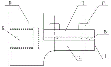
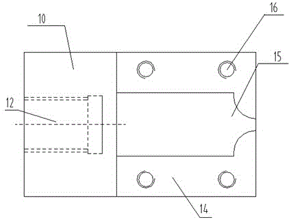
The invention discloses a clamping device and an experiment method for a split Hopkinson torsion bar test piece, and belongs to the field of impact dynamics experiments. The clamping device comprises a connector and a clamping part. The connector is of a cylinder structure, a circular blind hole is formed in the connector, an internal thread is arranged in the hole, and the connector is connected with an incidence bar or a transmission bar through the thread. The clamping part comprises a pressing block and a base, the pressing block is arranged above the base in a buckled mode, the base and the connector are fixed into a whole, a groove is formed in the upper surface of the base and is of a flat structure, the body of the groove is square, the end of the groove is in a horn shape, the pressing block is of a hexahedron structure, the upper surface of the pressing block is parallel with the lower surface of the pressing block, screw holes are formed in the periphery of the pressing block, screw holes are formed in the portion, corresponding to the pressing block, of the base, and the pressing block and the base are connected and fixed through screws. By means of the clamping device and the experiment method for the split Hopkinson torsion bar test piece, the problems of difficulty of thread machining of a composite and nonuniformity in the high-strength adhesive bonding process are avoided, and a powerful foundation is laid for studying the constitutive relation of a fiber composite under dynamic tension.

Description

technical field [0001] The invention relates to a clamping device and an experimental method for a separated Hopkinson rod test piece, belonging to the field of mechanical testing devices. Background technique [0002] Composite material, as an anisotropic heterogeneous material with a high tensile / shear strength ratio, must consider the stress concentration problem caused by the end effect, that is, the influence of the contact surface between the experimental rod and the specimen. Therefore, in the dynamic tensile experiment, the connection between the experimental rod and the specimen must consider the following issues. ① The stress concentration between the loading rod and the sample must be minimized; ② Try to avoid the mismatch of wave impedance between the loading rod and the sample to reduce the weakening of the effective pulse load caused by the reflection of the stress wave, which is conducive to waveform analysis ;③The tensile load is preferably transmitted to th...

Claims


Application Information

Patent Timeline
IPC IPC(8): G01N3/04G01N3/08
CPCG01N3/04G01N3/08
Inventor 王志华雷建银董鹏飞李世强
Owner TAIYUAN UNIV OF TECH
Learn More