Extra-high-voltage current transformer verification system

A UHV current and transformer calibration technology, applied in the direction of instruments, measuring electrical variables, measuring devices, etc., can solve problems such as no way to measure, unsatisfactory, difficult electrical parameters, etc., to improve calibration capabilities and work efficiency, The effect of reducing capacity and volume and reducing the cost of manpower and material resources

Inactive Publication Date: 2016-03-23
STATE GRID JIANGSU ELECTRIC POWER CO ELECTRIC POWER RES INST +3
View PDF5 Cites 14 Cited by
  • Summary
  • Abstract
  • Description
  • Claims
  • Application Information

AI Technical Summary

Problems solved by technology

These two indirect test methods avoid the problem of excessive requirements on the capacity of the current booster, voltage regulator and on-site power supply, and greatly reduce the volume and weight of the equipment carried in the on-site test. However, the indirect test methods cannot meet the requirements of "JJG1021- 2007 "Power Transformer" verification regulations, the real error of the current transformer under the condition of large current cannot be obtained, which reduces the reliability and authenticity of the test data
According to the statistical results of on-site verification of UHV current transformers, there are many cases where the upper limit error of current transformers is out of tolerance, especially near the rated current range. As the test current increases, the error increases. The reason for this phenomenon may be It is because the coil material of the current transformer is vibrated during installation and transportation, which causes the relative magnetic permeability of the iron core to decrease, and the saturation of the magnetic circuit near the rated current causes a sharp change in the error, so the small current extrapolation method cannot find this phenomenon, resulting in The verification data is not true and reliable; there are many problems in the calculation method of small voltage measurement. First, although the principles of current transformers are similar, but for the same type of current transformers to be verified, the ideal mathematical model and the actual current transformer It is difficult to determine the degree of equivalence between them. Although it can be verified by comparison and verification through simulation and a large number of experiments, the workload is undoubtedly huge; secondly, even if a mathematical model of a type of...

Method used


Image

  • Extra-high-voltage current transformer verification system
  • Extra-high-voltage current transformer verification system
  • Extra-high-voltage current transformer verification system

Examples


Embodiment Construction

[0021] The present invention will be further described below in conjunction with the accompanying drawings.

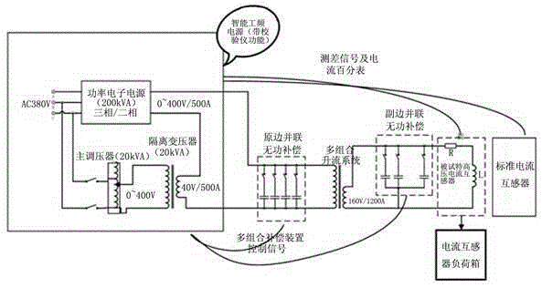
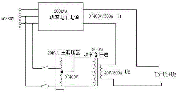
[0022] As shown in the figure, a UHV current transformer calibration system includes an intelligent industrial frequency power supply, a multi-combination reactive power compensation device, a multi-combination current boosting system, a standard current transformer, and a current transformer load box; among them, the multi-combination One side of the primary part of the reactive power compensation device is connected to the output terminal of the intelligent industrial frequency power supply, and the other side of the primary part of the multi-combination reactive power compensation device is connected to the input terminal of the multi-combination boosting system; the secondary part of the multi-combination reactive power compensation device One side of the multi-combination step-up system is connected to the output end of the multi-combination reactive power compensa...


PUM


Abstract

The invention discloses an extra-high-voltage current transformer verification system. The system comprises an intelligent power frequency power source, a multi-combination reactive power compensator, a multi-combination upflow system, a standard current transformer and a current transformer load bank. According to the invention, by use of a modern power electronic conversion technology according to which a three-phase-to-single-phase power electric electronic power supply and an electrical power supply are connected in series, an adaptive reactive compensation technology and an intelligent detection technology, load parameters of an extra-high-voltage GIS pipeline primary test loop are intelligently and efficiently analyzed, and reactive compensation is carried out automatically according to the load parameters, such that the capacities and the volumes of an onsite power supply and an upflow device are greatly reduced, integration and miniaturization of scattered detection devices are realized, the onsite verification capability and the work efficiency are improved, the cost of manpower and material resources is decreased, and the problem of incapability of detecting an extra-high-voltage current transformer according to detection regulations in a field is solved.

Description

technical field [0001] The invention belongs to the technical field of ultra-high voltage testing, in particular to an ultra-high voltage current transformer calibration system. Background technique [0002] The UHV GIS current transformer has the characteristics of large transformation ratio, long pipeline loop, high integration, and full enclosure. The current transformer cannot be isolated during on-site verification, and a long pipeline busbar and some electrical components need to be brought. The circuit impedance is large. For example, the GIS current transformer test circuit in Lanzhou East UHV Substation is as long as 390 meters. In this way, the test power supply and current-raising equipment capacity required for on-site verification of UHV GIS current transformers with large transformation ratio and long primary circuit Huge, for example, a 4000A / 1A UHV current transformer in a 200-meter GIS circuit requires a power supply capacity of about 800kVA at 120% of the r...

Claims


Application Information

Patent Timeline
IPC IPC(8): G01R35/02
CPCG01R35/02
Inventor 徐敏锐卢树峰黄奇峰杨世海王忠东陈铭明赵双双李志新陈刚吴桥孙军徐灿
Owner STATE GRID JIANGSU ELECTRIC POWER CO ELECTRIC POWER RES INST
Why Eureka
Try Eureka