Double-rotational parabolic dipole antenna

A vibrator antenna and paraboloid technology, applied in the field of standard radiation source antennas, can solve the problems of deviation from the horizontal direction and low gain, and achieve the effects of enhancing gain, ensuring impedance matching, and achieving horizontal omnidirectionality.

Active Publication Date: 2016-03-23
BEIJING INST OF RADIO METROLOGY & MEASUREMENT
View PDF2 Cites 2 Cited by
  • Summary
  • Abstract
  • Description
  • Claims
  • Application Information

AI Technical Summary

Problems solved by technology

[0003] In order to strengthen the electromagnetic energy confinement capability and gain of the ultra-broadband dipole antenna in the horizontal direction, the present invention proposes a double-rotating parabolic dipole antenna, which solves the problem that the main beam direction of the current standard radiation source antenna deviates from the horizontal direction with different frequencies, resulting in low gain.

Method used


Image

  • Double-rotational parabolic dipole antenna
  • Double-rotational parabolic dipole antenna
  • Double-rotational parabolic dipole antenna

Examples


Embodiment Construction

[0028] In order to achieve the object of the present invention, an embodiment of the present invention provides a dual-rotating parabolic dipole antenna, which aims to enhance the gain of the ultra-wideband dipole antenna in the horizontal direction. Various embodiments of the present invention will be further described in detail below in conjunction with the accompanying drawings. Apparently, the described embodiments are only some of the embodiments of the present invention, not all of them. Based on the embodiments of the present invention, all other embodiments obtained by persons of ordinary skill in the art without making creative efforts belong to the protection scope of the present invention.

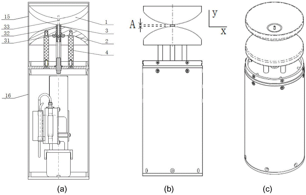
[0029] figure 1 It is a structure embodiment of a double rotating parabolic dipole antenna (including an electrical package), including (a) a vertical section view, (b) a side view, and (c) a perspective view. The components of the dual-rotating parabolic dipole antenna includ...


PUM


Abstract

The invention discloses a double-rotational parabolic dipole antenna, which is used for solving of low gain caused by deviation of a main beam direction of the current standard radiation source antenna from a horizontal direction with different frequencies. The double-rotation parabolic dipole antenna comprises an upper oscillator, a lower oscillator and a connection device, wherein the outer surfaces of the upper oscillator and the lower oscillator are rotational paraboloids with same shape, the connection device comprises a coaxial connector, an inner conductor and an insulator, and the end surface of a second end of the insulator is conformal to the outer surface of the upper oscillator. As the typical embodiment of the invention, the exponential term coefficient of a rotational curvilinear equation of the rotational paraboloids is 0.06, the slope is 0.1, the radiation distance is 2 millimeters, and the maximum radius value of the upper oscillator and the lower oscillator is 48.5 millimeters. With the double-rotational parabolic dipole antenna disclosed by the typical embodiment of the invention, a horizontal omnibearing standard radiation field in a range of ultra wide band (1GHz to 18GHz) is achieved; and with the adoption of a mode of changing oscillator gap to a curve distance, the gain of the ultra wide band dipole antenna in the horizontal direction is enhanced.

Description

technical field [0001] The invention relates to the field of radio measurement, in particular to a standard radiation source antenna for RE102 comparison test and electromagnetic environment monitoring. Background technique [0002] The standard radiation source antenna is the transmitting antenna of the standard radiation source used in the RE102 comparison test, and is used to transmit ultra-wideband horizontal omnidirectional radiation signals. RE102 is a test experiment in the electromagnetic emission and sensitivity requirements of military equipment and subsystems. The frequency range of electric field radiation emission is 10kHz~18GHz (this design is designed for the high frequency band 1GHz~18GHz in the RE102 test). The standard radiation source antenna can also be applied to electromagnetic environment monitoring, shielding effectiveness test, normalized site attenuation measurement in anechoic room and site standing wave ratio measurement. The standard radiator an...

Claims


Application Information

Patent Timeline
Patent Type & Authority Applications(China)
IPC IPC(8): H01Q1/38H01Q1/50H01Q19/17
CPCH01Q1/38H01Q1/50H01Q19/17
Inventor 黄建领李贵兰穆晨晨马蔚宇袁岩兴
Owner BEIJING INST OF RADIO METROLOGY & MEASUREMENT
Why Eureka
Try Eureka