
Wireless charging receiver end and manufacturing method thereof

A technology of wireless charging and manufacturing method, which is applied in the direction of circuits, inductors, electrical components, etc., can solve the problems of increased internal resistance of coils, waste of copper foil, and increased AC resistance, and achieve overall thickness reduction, reduced loss, and increased effect of diameter

Inactive Publication Date: 2016-03-23
麦格磁电科技(珠海)有限公司
View PDF9 Cites 4 Cited by
  • Summary
  • Abstract
  • Description
  • Claims
  • Application Information

AI Technical Summary

Problems solved by technology

[0003] Traditional receiver coils usually use large-diameter single-strand copper wire or double-strand copper wire, which has low resistance, high charging efficiency, and low heat generation, but its thickness is relatively thick, which is not conducive to the thinning and thinning of electronic products, especially mobile communication products such as mobile phones. trend
[0004] Therefore, double-sided flexible circuit board FPC is usually used to replace the above-mentioned coil at present. Although FPC can reduce the thickness of the overall coil, its AC resistance increases; in addition, FPC still cannot solve the problem of increasing the thickness of the receiving end of the lead-out line. When manufacturing coils, the planar coil and the external lead-out wires are usually processed on one side of the FPC first, and the internal lead-out wires are processed on the other side of the FPC, and then through holes are opened on the FPC board to realize electrical connection between the internal lead-out wires and the planar coil. Sexual connection; the manufacturing process of this coil not only wastes a lot of copper foil, which increases the cost, but also the thickness of the manufactured coil includes the thickness of two layers of copper foil and the thickness of one layer of FPC substrate. is relatively small, so the internal resistance of the coil increases

Method used


Image

  • Wireless charging receiver end and manufacturing method thereof
  • Wireless charging receiver end and manufacturing method thereof
  • Wireless charging receiver end and manufacturing method thereof

Examples


Embodiment 2

[0041] Method Embodiment 2: A method for manufacturing a wireless charging receiving end. In this embodiment, a planar coil is fabricated on a single-sided FPC, including the following steps:

[0042] A. Processing of receiving coil

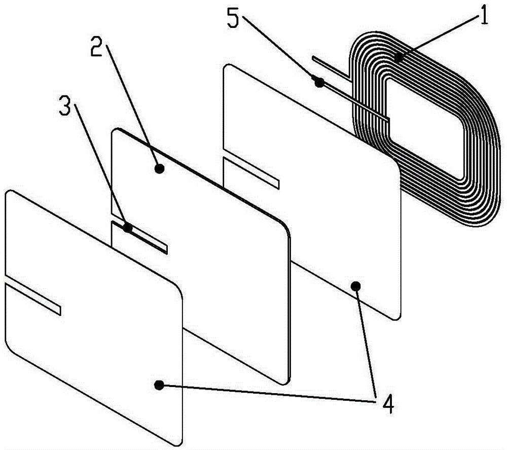
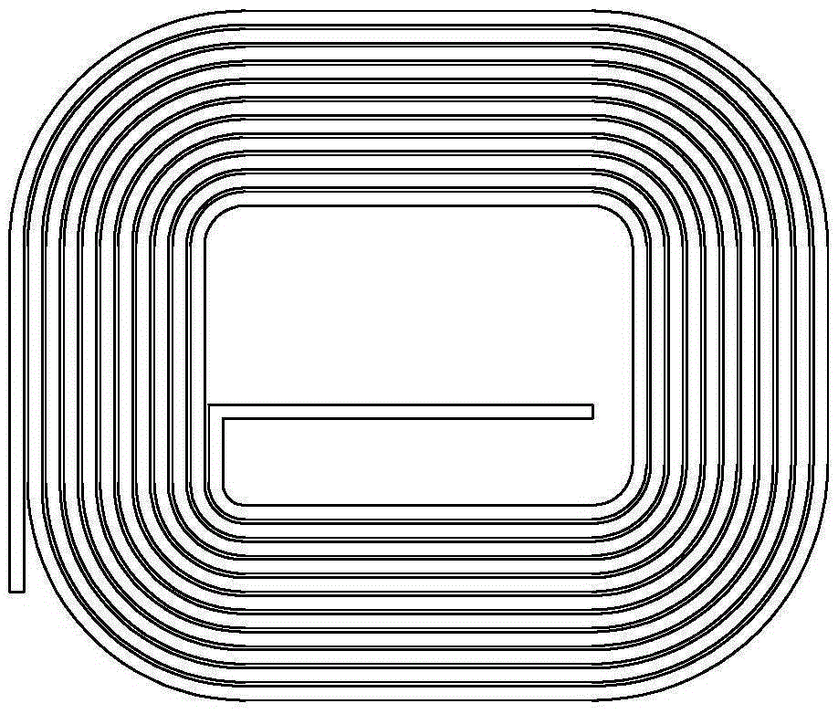
[0043] A1. Process the planar coil and the inner and outer lead-out lines on the single-sided flexible circuit board FPC, wherein the outer lead-out lines are directly set at the lead-out position and extend outward from the outermost circle of the planar coil (such as Figure 4 shown);

[0044] A2. Cut the three edges where the inner lead wire and the coil are not connected;

[0045] A3. Insulate the part where the cut inner lead wire is in contact with the coil main body;

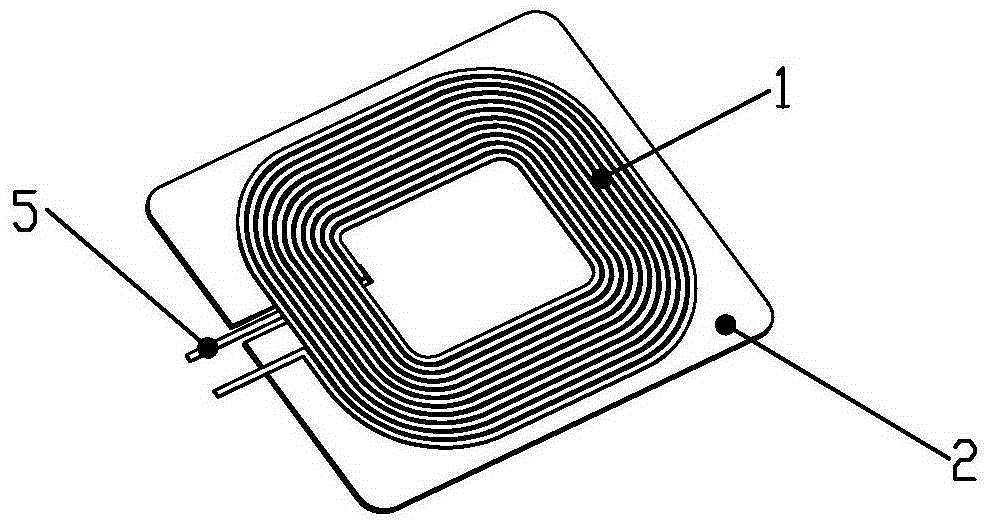
[0046] A4. Fold the inner lead wire after insulation treatment to the surface of the coil. The bending angle can be any angle according to the needs, preferably 90° or 45°, so that the outgoing wire directions of the inner and outer lead wires are consistent;

[0047] B. ...


PUM


Abstract

The invention discloses a wireless charging receiver end a manufacturing method thereof. The wireless charging receiver end comprises a receiving coil and a magnetic shielding sheet, wherein the lead section of the receiving coil is non-circular and the magnetic shielding sheet is arranged under the receiving coil. The wireless charging receiver end is characterized in that the magnetic shielding sheet is provided with at least one groove and an inner outgoing line of the receiving coil is arranged on the surface of the receiving coil in a folded way and is mounted in the at least one groove. With adoption of the structure and the manufacturing process of the product, the thickness of the coil can be reduced by the thickness of one copper foil layer; since the overall thickness of the coil is reduced largely, the thickness of single copper foil layer can be increased properly and further the diameter of the coil can be increased; therefore, the inner resistance of the coil can be lowered and the loss can be reduced.

Description

technical field [0001] The invention relates to the field of wireless power transmission, in particular to a wireless charging receiving end and a manufacturing method thereof. Background technique [0002] The receiving end of wireless charging is usually composed of a receiving coil, a magnetic shielding sheet, a power management circuit, etc. The receiving coil receives the electric energy transmitted by the transmitting end due to electromagnetic induction, and the magnetic shielding sheet increases the efficiency of receiving and reduces energy loss. The power management circuit is connected with the receiving coil, and converts the electric energy of the receiving coil into a current of a certain voltage, current or frequency that can be used by the load. [0003] The traditional receiver coil usually uses large-diameter single-strand copper wire or double-strand copper wire, which has low resistance, high charging efficiency, and low heat generation, but its thickne...

Claims


Application Information

Patent Timeline
IPC IPC(8): H02J50/10H01F38/14H01F27/36
Inventor 蔚晓东刘志坚
Owner 麦格磁电科技(珠海)有限公司
Learn More