Microscopic endoscope system

A technology of endoscope and microscope objective lens, which can be used in endoscopy, medical science, surgery, etc., and can solve the problems of low imaging magnification, inability to observe tissue morphological changes and cell microstructure, etc.

Inactive Publication Date: 2016-04-06
GUANGDONG OPTO MEDIC TECH CO LTD
View PDF13 Cites 5 Cited by
  • Summary
  • Abstract
  • Description
  • Claims
  • Application Information

AI Technical Summary

Problems solved by technology

[0005] The object of the present invention is to provide a microendoscope system to solve the problem of low imaging magnification of the prior art endoscope system and the inability to observe the morphological changes of tissues and the microscopic structure of cells

Method used


Image

  • Microscopic endoscope system
  • Microscopic endoscope system
  • Microscopic endoscope system

Examples


Embodiment 1

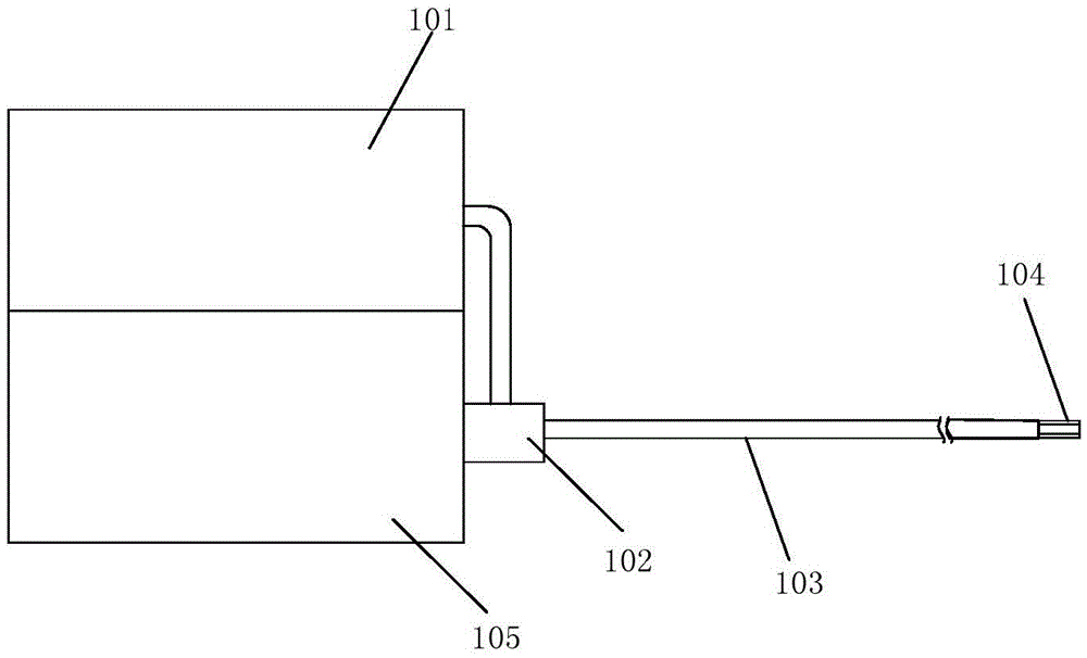
[0033] refer to figure 1 , the present invention provides a microendoscope system, including an illumination unit 101 that provides illumination light for the endoscope, an imaging and image processing unit 105 that captures images of human tissue and performs image processing, wherein the microendoscope system It also includes an endoscope microprobe 104, which enters the body cavity through the forceps hole of the endoscope system and performs microscopic imaging of the target tissue, and also includes a transmission endoscope microprobe 104. The optical fiber imaging bundle 103 of the formed target image also includes an image output and illumination input unit 102, the image output and illumination input unit 102 couples the illumination light output by the illumination unit 101 into the optical fiber imaging bundle 103, and The image transmitted by the optical fiber image transmission bundle 103 is input to the camera and image processing unit 105 .

[0034] refer to f...

Embodiment 2

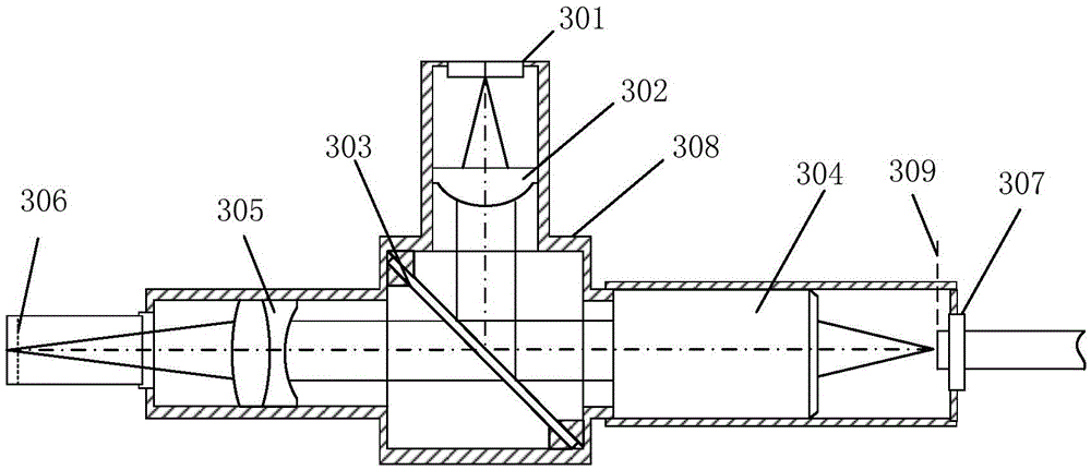
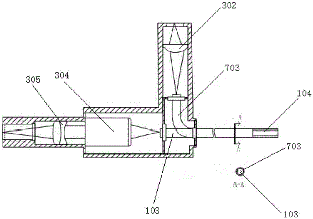
[0046] refer to image 3 , in this embodiment, the image output and illumination input unit 102 includes a condenser lens 302 that collects illumination light, an illumination fiber bundle 703 and an optical fiber image transmission bundle 103, a microscope objective lens 304, and a lens tube lens 305. The illumination fiber bundle 703 is The interface between the image output and illumination input unit 102 and the optical fiber image transmission bundle 103 begins to wrap around the outer edge of the optical fiber image transmission bundle 103, the focal point of the condenser is located on the end face of the illumination optical fiber bundle 703, and the focal point of the microscope objective lens is located at the end surface of the optical fiber transmission bundle 703. on the end face of the image beam 103 . In this embodiment, the setting of a beam splitter is omitted, the light is directly coupled into the lighting fiber bundle 703, and then the light is transmitted ...

Embodiment 3

[0048] refer to Figure 4 , in this embodiment, the image output and illumination input unit 102 includes a condenser lens 302 that collects illumination light, a multimode optical fiber 803, an optical fiber image bundle 103, a microscope objective lens 304, and a barrel lens 305. The multimode optical fiber 803 At the interface between image output and illumination input unit 102 and optical fiber image transmission bundle 103, it is set at the center of the optical fiber image transmission bundle 103, the focal point of the condenser 302 is located on the end face of the multimode optical fiber 803, and the focal point of the microscope objective lens Located on the end face of the optical fiber image transmission bundle.


PUM


Abstract

The invention discloses a microscopic endoscope system which comprises an illuminating unit, a camera shooting and image processing unit, an endoscope microscopic probe, an optical fiber image transmitting bundle and an image output and illumination input unit. The illuminating unit provides illumination light for an endoscope; the camera shooting and image processing unit shoots a body tissue image and processes the image; the endoscope microscopic probe enters the body cavity through a pincers channel hole of the endoscope system and carries out microimaging on the target tissue; the optical fiber image transmitting bundle transmits a target image formed through the endoscope microscopic probe; the image output and illumination input unit couples illuminating light output by the illuminating unit into the optic fiber image transmitting bundle and inputs the image transmitted out by the optic fiber image transmitting bundle into the camera shooting and image processing unit. The system solves the problems that an endoscope system in the prior art is low in imaging override, and the morphologic change and the cell microstructure of the tissue can not be observed.

Description

technical field [0001] The invention relates to the field of medical instruments, in particular to a microendoscope system. Background technique [0002] Medical endoscope is a common medical device, which can generally enter the body through the natural passages of the human body, such as the oral cavity, nasal cavity, etc., or through small incisions made artificially on the human body, so as to realize the inspection of diseased organs in the human body. In recent years, the clinical endoscopic technology has made great progress, such as high-definition endoscopy, zoom endoscopy and narrow-band imaging endoscopy (Narrow-band Imaging, NBI) and so on. These new technologies can achieve clearer imaging of the lesion, magnify the imaging of the lesion, or highlight the microvascular structure of the lesion. The disease detection rate of endoscopy has been further improved. [0003] For example, Chinese patent CN200780016642 provides an image processing device for an endosco...

Claims


Application Information

Patent Timeline
Patent Type & Authority Applications(China)
IPC IPC(8): A61B1/00A61B1/05A61B1/07
CPCA61B1/00009A61B1/00013A61B1/00131A61B1/00165A61B1/051A61B1/0661A61B1/07
Inventor 刘满林揭光锦易遥王翰林安昕张浠
Owner GUANGDONG OPTO MEDIC TECH CO LTD
Why Eureka
Try Eureka