Device for achieving flue gas power generation and removing harmful substance in flue gas simultaneously

A technology for harmful substances and flue gas, which is used in combination devices, gas treatment, vapor condensation, etc. to achieve the effect of stable chemical properties

Inactive Publication Date: 2016-04-06
XIANGNAN UNIV +1
View PDF10 Cites 2 Cited by
  • Summary
  • Abstract
  • Description
  • Claims
  • Application Information

AI Technical Summary

Problems solved by technology

The system also does not remove harmful substances in the flue gas

Method used


Image

  • Device for achieving flue gas power generation and removing harmful substance in flue gas simultaneously
  • Device for achieving flue gas power generation and removing harmful substance in flue gas simultaneously

Examples


Embodiment Construction

[0014] The present invention will be further described below in conjunction with the accompanying drawings and embodiments.

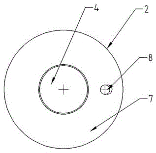
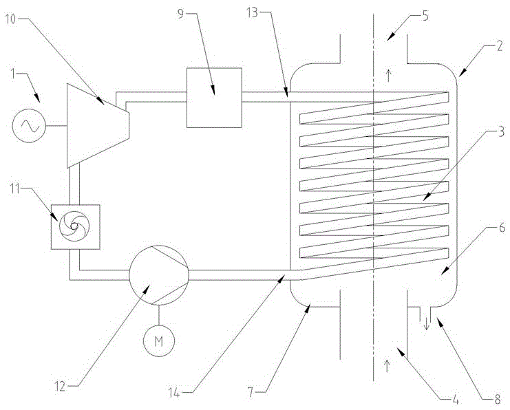
[0015] attached Figure 1-2 Represents a device for generating electricity from flue gas while removing harmful substances in flue gas, including a flue gas treatment system, an energy conversion system and a generator 1; the flue gas treatment system consists of a casing 2, a heat exchanger 3, a flue gas inlet 4, The flue gas outlet 5 is composed of; the heat exchanger 3 is placed in the shell 2 and is composed of a coil with fins on the surface; the space enclosed between the inner surface of the shell 2 and the outer surface of the heat exchanger 3 is the flue gas channel 6 The flue gas inlet 4 is below the casing 2, and the flue gas outlet 5 is above the casing 2; at the interface between the inner surface of the lower part of the casing 2 and the flue gas inlet 4, an annular condensed water collection tank 7 is formed, and the condensed water colle...


PUM

PropertyMeasurementUnit
boiling pointaaaaaaaaaa
critical temperatureaaaaaaaaaa
critical pressureaaaaaaaaaa

Abstract

The invention relates to device for achieving flue gas power generation and removing harmful substance in flue gas simultaneously. The device comprises a flue gas treatment system, a transduction system and an electric generator; the flue gas treatment system is composed of a shell, an evaporative condenser, a flue gas inlet and a flue gas outlet; the transduction system comprises a working medium evaporator, a working medium turbine, a condenser and a working medium compressor which are sequentially connected; the output end of the working medium compressor and the input end of the working medium evaporator are connected with a working medium outlet and a working medium inlet of a heat exchanger respectively; the working medium turbine drives the electric generator. According to the device for achieving flue gas power generation and removing harmful substance in the flue gas simultaneously, heat in flue gas is utilized to conduct heating, so that an organic working medium is evaporated, the working medium turbine is pushed to generate power, the heat utilization rate is high, and meanwhile harmful substances in the flue gas can be removed.

Description

technical field [0001] The invention relates to a device for generating electricity with flue gas while removing harmful substances in the flue gas, and belongs to the technical field of gas pollution control. Background technique [0002] The flue gas produced by industrial furnaces has a high temperature, contains a large amount of water vapor, and has a high energy value. The existing technology adopts a heat exchange device in the flue gas channel, using the heat in the flue gas to heat water to form a hot water cycle, and the hot water further heats the organic working medium, so that the organic working medium evaporates and drives the steam turbine to generate electricity. Pollutants and harmful gases are the main pollutants of air pollution, causing important air pollution phenomena such as smog and acid rain. In the prior art, the harmful substances in the flue gas cannot be removed, the temperature of the flue gas must be controlled above the dew point of the flue...

Claims


Application Information

Patent Timeline
Patent Type & Authority Applications(China)
IPC IPC(8): B01D53/00B01D5/00B01D50/00
CPCB01D53/002B01D2257/602B01D50/40
Inventor 杨德俊冯纪南王睿琪
Owner XIANGNAN UNIV
Why Eureka
Try Eureka