Automatic processing production line for metal sheets

A metal sheet and production line technology, applied in the direction of manufacturing tools, other manufacturing equipment/tools, etc., can solve the problems of increased working time, low degree of automation, large noise and vibration, etc., to improve work efficiency, small material transmission distance, and land occupation. small area effect

Active Publication Date: 2016-04-06
江苏扬力数控机床有限公司
7 Cites 18 Cited by

AI-Extracted Technical Summary

Problems solved by technology

Generally, after stamping and forming of auto parts, trimming and hole cutting are often required, and ordinary materials are acceptable, but the high-strength steel plate is too high in strength, and the noise and vibration are r...

Method used

Fixed seat and foundation are rigidly fixed, and column is rigidly connected with fixed seat, and rear arm cooperates with column rigid cylindrical surface, and two degrees of freedom of up and down motion and rotational motion are controllable, and rear arm and forearm are hinged in the middle, and rotation is controllable, and forearm Suction cups are respectively hinged at both ends, and the rotation of each suction cup is controllable. Two suction cups adjust the height of the pole and the angle of the spherical pair, one of which absorbs the flat sheet (that is, the suction cup for flat parts 123), and the other absorbs three-dimensional parts (that is, the suction cup for three-dimensional parts), which is convenient for sucking ...

Abstract

The invention discloses an automatic processing production line for metal sheets, relates to the field of automobile sheet processing, in particular to the automatic processing production line for metal sheets. The automatic processing production line is simple in structure and is reasonable in layout, saves working time and improves working efficiency. A stamping processing unit is arranged on a foundation by virtue of a damping mechanism; the stamping processing unit is used for processing blank sheets into semi-finished products; a stamping loading and unloading mechanical hand is used for gripping the blank sheets of a blank warehouse and gripping the semi-finished products to a semi-finished product warehouse; and a gap is arranged between a counterweight platform and a vibration isolating slot, and a spring is arranged in the gap. According to the automatic processing production line for metal sheets, the gap is arranged between the counterweight platform and the vibration isolating slot, and sand is arranged in the gap. The automatic processing production line realizes processing such as automatic forming, trimming, opening cutting and the like, is small in floor space, is small in material transmission distance, is precise and efficient, is high in working efficiency, is capable of realizing cutting processing without stop, is high in efficiency, and is beneficial for improving the working efficiency of the integral production line.

Application Domain

Technology Topic

Image

  • Automatic processing production line for metal sheets
  • Automatic processing production line for metal sheets
  • Automatic processing production line for metal sheets

Examples

  • Experimental program(1)

Example Embodiment

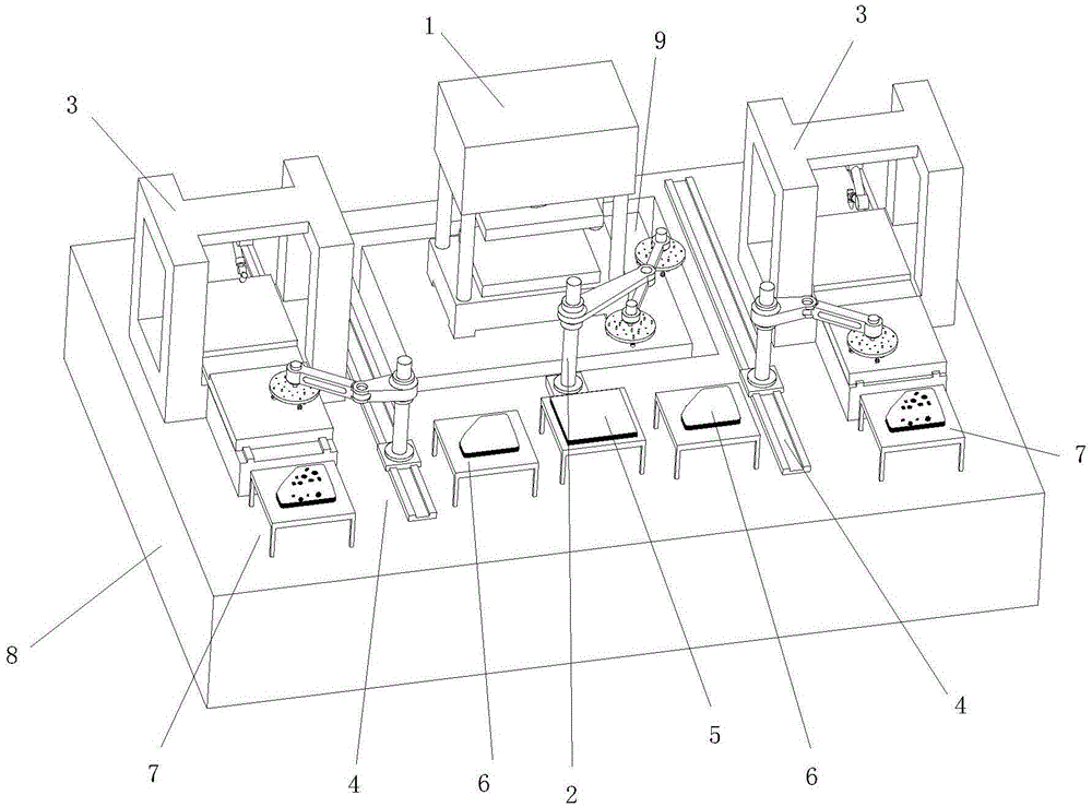
[0041] The invention is like Figure 1-8 As shown, it includes a punching processing unit 1 (ie a press), a punching and unloading manipulator 2, n groups of laser cutting processing units 3, and k groups of laser cutting and feeding mechanisms 4 set on the foundation 8, where n≥1, n Take an integer, k≥1, k takes an integer;
[0042] In work, the number of laser cutting processing units and laser cutting loading and unloading mechanisms can be different. For example, four groups of laser cutting processing units can be used, but only two sets of laser cutting loading and unloading mechanisms are used. Each group of laser cutting loading and unloading mechanisms is two groups ( Or more) Laser cutting processing unit service, this case is preferred, n=k=2.
[0043] The punching processing unit 1 is arranged on the foundation through a vibration damping mechanism, and the punching processing unit is used to process a blank sheet into a semi-finished product,
[0044] The punching and loading manipulator 2 is used for grabbing the blank plates of the blank storage 5 and grabbing the semi-finished products to the semi-finished storage 6;
[0045] The n groups of laser cutting and processing units 3 and k groups of laser cutting and loading and unloading mechanisms 4 are arranged correspondingly. The laser cutting and processing units are used to process semi-finished products into finished products. The laser cutting and loading and unloading mechanisms 4 are used to grab the semi-finished products in the material storage 6 Semi-finished products and grabbing finished products to finished product warehouse 7.
[0046] In the work of the present invention, the number of n groups of laser cutting processing units and k groups of laser cutting and loading and unloading mechanisms can be set and arranged according to specific work situations. The two sides of the punching processing unit can be arranged in parallel, or it can be arranged in a ring around the punching The layout around the processing unit is compact to improve work efficiency.
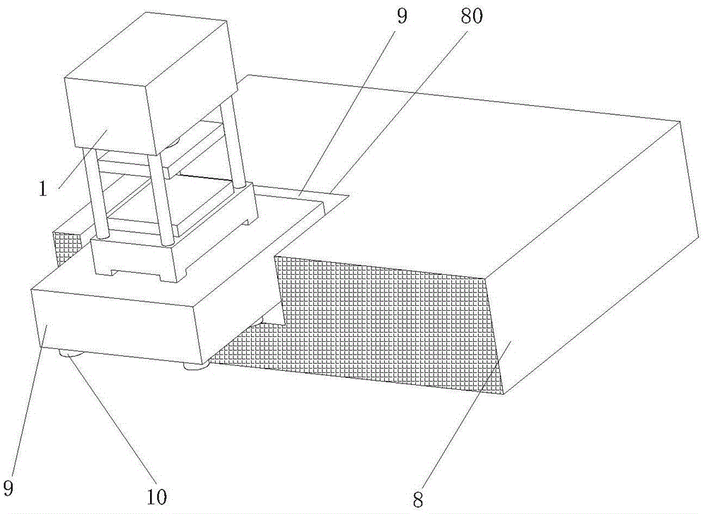
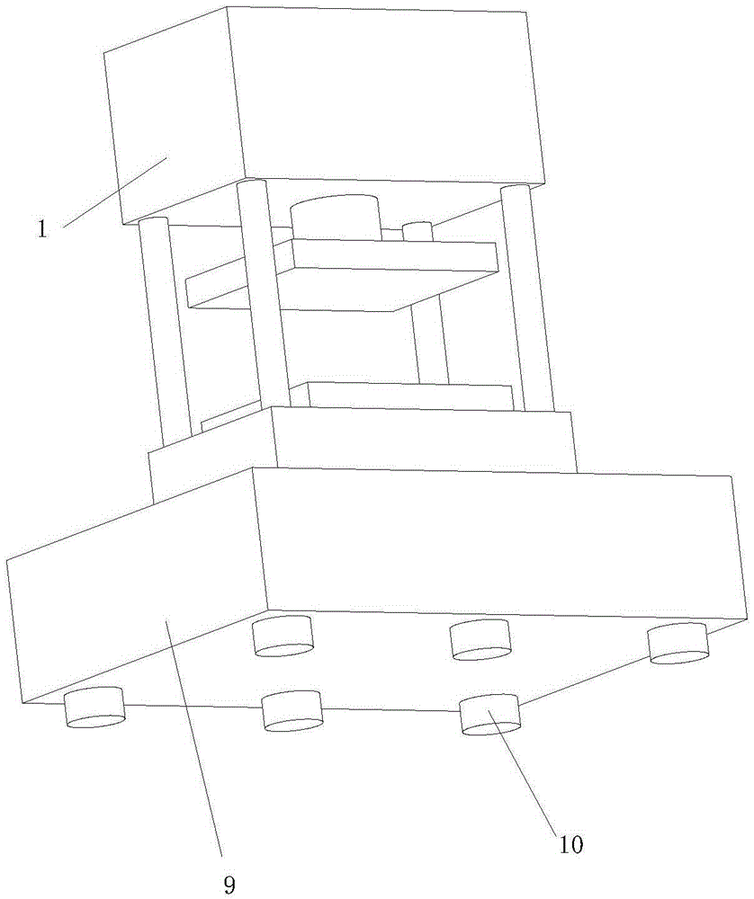
[0047] The vibration damping mechanism is as follows: a vibration isolation groove 80 is provided on the foundation 8, and the stamping processing unit is set in the vibration isolation groove 80 through a counterweight platform 9. The counterweight platform can be a reinforced concrete structure. The function of the counterweight platform is to reduce the ground vibration caused by the impact load of the press, and reduce the vibration transmission of the press vibration to the surrounding foundation. The vibration isolation slot further prevents the transmission of vibration to the surrounding foundation. . Large-mass counterweight platform is extremely beneficial to vibration isolation.
[0048] It also includes a shock absorber 10, which is all arranged on the bottom surface of the counterweight platform. The shock absorber plays the role of vibration isolation. The shock absorber is preferably a coil spring shock absorber, or a rubber spring shock absorber. The three measures of counterweight platform, shock absorber and vibration isolation groove can effectively reduce the vibration of the foundation caused by the vibration of the press, which is particularly beneficial for laser cutting, feeding mechanism and peripheral precision equipment.
[0049] A gap 11 is provided between the counterweight platform 9 and the vibration isolation groove 80, and a spring is provided in the gap 11; the spring is provided to reduce vibration and further prevent the transmission of vibration to the surrounding foundation.
[0050] A gap is provided between the counterweight platform 9 and the vibration isolation groove 80, and the gap 11 is provided with sand; the sand is provided to reduce vibration and further prevent the transmission of vibration to the surrounding foundation.
[0051] Such as Figure 4 As shown, the laser cutting processing unit 3 includes a frame 31, a pair of gantry columns 32 are respectively provided on both sides of the frame, a cross beam 33 is provided in the middle of the top surface of the pair of gantry columns 32, and the bottom surface of the cross beam is connected An articulated manipulator 34 is provided to make the articulated manipulator inverted. The frame 31 is slidably connected with a worktable 35, and the worktable 35 has an A station 36 and a B station 37.
[0052] The base of the joint manipulator is fixedly connected with the lower surface of the beam to form an inverted suspension. The manipulator has an upside-down four-post gantry structure with good rigidity, a large effective cutting range, and good accuracy retention; the cutting head 38 is installed at the end of the articulated robot's arm, and three-dimensional cutting is realized through the movement of the robot; A and B are set on the worktable Two stations, when one station is in the cutting operation, the other station can carry out automatic loading and unloading operations to ensure that the equipment does not stop processing, and the efficiency is high.
[0053] Such as Figure 5 As shown, the laser cutting and loading and unloading mechanism includes a guide rail 41, a base 42, a column (ie, column two 43), a big arm 44, a small arm 45, and a suction cup 12. The base 42 is slidably connected to the guide rail 41, so The upright is fixedly connected to the base 42, the big arm 44 can be raised and lowered and rotatably connected to the upright, the small arm 45 is hinged to the big arm 44, and the suction cup 12 is hinged to the small Arm.
[0054] A sliding pair is formed between the base and the guide rail, the linear motion of the base is controllable, and it can be driven by linear motors, gears and racks; the base and the column are rigidly connected; the column and the boom are matched with the cylindrical surface, and the rotation and the two degrees of freedom are controllable. It can rotate and move up and down; the big arm is hinged with the forearm, and the rotation is controllable; the suction cup is hinged with the forearm, and the rotation is controllable.
[0055] Such as Figure 8 As shown, the punching and unloading manipulator includes a fixed seat 21, a column (ie, column one 22), a forearm 23, a rear arm 24, and a pair of suction cups 12. The fixed seat 21 is rigidly fixed to the foundation 8, and the column is arranged at On the fixed seat 21, the rear arm 24 can be raised and lowered and rotatably connected to the column, the forearm 23 (that is, the middle position of the forearm) is hinged on the rear arm, and a pair of suction cups 21 are respectively hinged on The two ends of the forearm 23.
[0056] The fixed base is rigidly fixed with the foundation, the column is rigidly connected with the fixed base, the rear arm is matched with the rigid cylindrical surface of the column, the two degrees of freedom of up and down movement and rotation are controllable, the rear arm and the forearm are hinged, and the rotation is controllable. The two ends of the forearm are separately Suction cups are hinged, and the rotation of each suction cup is controllable. Two suction cups adjust the height of the support rod and the angle of the spherical surface, one of which sucks flat sheet material (that is, the suction cup 123 of the flat part), and the other sucks the three-dimensional parts (that is, the suction cup of the three-dimensional parts), which is convenient for sucking parts of different shapes and has good adaptability. .
[0057] The suction cup 12 includes a connecting disk 121, a plurality of supporting rods 121, and a plurality of electromagnets 123. The connecting disk 121 is provided with a plurality of circular holes 1210, the supporting rods 122 are arranged in the circular holes 1210, and the electromagnets 123 corresponds to the support rod 122 one-to-one, and the electromagnet 123 and the support rod 122 are connected by a spherical pair.
[0058] During work, a round hole is set on the connecting plate, and the round hole is connected with the support rod. The support rod can be adjusted in height in the round hole. The support rod and the electromagnet are matched through a spherical pair; by adjusting the height of the support rod and the electromagnet Angle adjustment adapts to the curved surface of three-dimensional parts, such as Figure 7 As shown, the four support rods of the inner ring and the electromagnet absorb the plane, the four support rods of the outer ring are elongated and the angle of the electromagnet is adjusted to adapt to the surface of the three-dimensional part, thereby reliably sucking the three-dimensional part. The temperature of the finished product is relatively high, so electromagnets are needed to absorb.
[0059] The support rod 122 is a telescopic rod, and the support rod can be fixedly arranged to facilitate expansion and contraction. Through the adjustment of the height of the support rod and the adjustment of the angle of the spherical surface, the electromagnet can adapt to the curved surfaces of different three-dimensional parts.

PUM

no PUM

Description & Claims & Application Information

We can also present the details of the Description, Claims and Application information to help users get a comprehensive understanding of the technical details of the patent, such as background art, summary of invention, brief description of drawings, description of embodiments, and other original content. On the other hand, users can also determine the specific scope of protection of the technology through the list of claims; as well as understand the changes in the life cycle of the technology with the presentation of the patent timeline. Login to view more.

Similar technology patents

Adaptive correction method for color gray-scale image of display

ActiveCN102629466AGuaranteed display qualitySmall footprintCathode-ray tube indicatorsImage propertiesCorrection method
Owner:NANJING JUSHA DISPLAY TECH

Classification and recommendation of technical efficacy words

Why Eureka
Try Eureka