
Biological denitrification device

A technology for biological denitrification and purification pool, applied in the field of biological denitrification, can solve the problems of limited application scope, low process flexibility, large space occupation, etc., and achieve the effect of reducing production cost, high process flexibility, and space saving

Inactive Publication Date: 2016-04-06
BEIJING YIPU INT WATER AFFAIRS +1
View PDF5 Cites 4 Cited by
  • Summary
  • Abstract
  • Description
  • Claims
  • Application Information

AI Technical Summary

Problems solved by technology

[0003] At present, the main structure of the existing biological denitrification device includes an aerobic tank and an anaerobic tank that are independent of each other. The bottom of the oxygen tank is usually equipped with an aeration device, through which the contact surface between the aerobic microorganisms and the air can be increased, thereby improving the reaction rate of the nitrification reaction and the purification ability of the sewage; but this existing biological denitrification device takes up Large space, low process flexibility, high energy consumption, high cost, limited scope of application

Method used


Image

  • Biological denitrification device

Examples


Embodiment 1

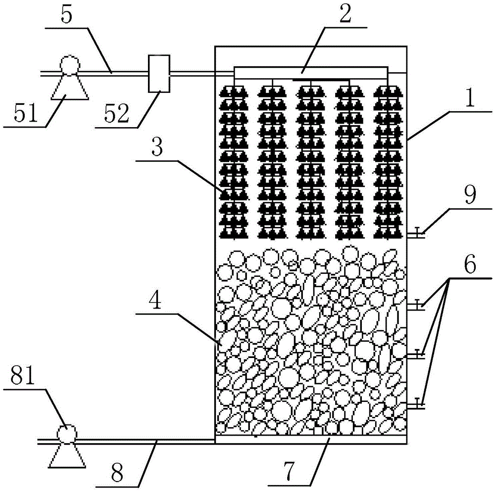
[0021] Such as figure 1 As shown, a biological denitrification device, its specific structure may include: a purification pool 1, a water distributor 2, a fiber packing 3 with aerobic nitrifying microorganisms attached, a solid packing 4 with anaerobic denitrifying microorganisms attached, a purification pool Water inlet pipe 5, purification tank water outlet 6, backwash air pan 7, backwash water inlet pipe 8 and backwash water outlet 9; water distributor 2 is located on the upper part of purification tank 1, and the water inlet of water distributor 2 is connected The pool inlet pipe 5 is connected; the fiber filler 3 is set in the purification tank 1 and is located below the water distributor 2; the solid filler 4 is set in the purification tank 1 and is located below the fiber filler 3; multiple purification tank outlets 6 It is located at different heights on the side wall of the purification tank 1, and the height of the water outlet 6 of each purification tank is lower th...

Embodiment approach

[0023] (1) The water distribution pipe of the water distributor 2 mainly has two functions: one is that when the sewage to be treated enters the water distributor 2 from the water inlet pipe 5 of the purification tank, the water distribution pipe of the water distributor 2 can discharge the sewage to be treated in the purification tank 1 distributes water evenly, and the other provides support for the fiber filler 3.

[0024] (2) Aerobic nitrifying microorganisms (the aerobic nitrifying microorganisms can be nitrosifying bacteria and nitrifying bacteria) are attached to the fibrous packing 3, and when the sewage to be treated flows out from the water distribution pipe of the water distributor 2, it contacts the fibrous packing 3, and The nitrification reaction occurs under the action of aerobic nitrifying microorganisms, thereby realizing the nitrification treatment of the sewage to be treated.

[0025] In practical application, the fiber filler 3 can be a plurality of tubular...


PUM


Abstract

The invention discloses a biological denitrification device. The biological denitrification device comprises a water distributor (2), a fibrous filler (3), a solid filler (4), a plurality of purifying tank water outlets (6), a back washing gas disk (7) and a back washing water outlet (9), wherein the water distributor (2) is arranged on the upper part of a purifying tank (1), and a water inlet of the water distributor (2) is communicated with a water inlet pipe (5) of the purifying tank (1); the fibrous filler (3) is arranged below the water distributor (2); the solid filler (4) is arranged below the fibrous filler (3); the plurality of purifying tank water outlets (6) are formed in the side wall of the purifying tank (1) at different heights, and the height of each purifying tank water outlet (6) is lower than the upper surface of the solid filler (4); the back washing gas disk (7) is arranged below the solid filler (4), and a water inlet of the back washing gas disk (7) is communicated with a back washing water inlet pipe (8); the back washing water outlet (9) is formed in the side wall of the purifying tank (1), and the height of the back washing water outlet (9) is higher than the upper surface of the solid filler (4). The biological denitrification device has the advantages of no need of an aerator, little occupied space, low operating energy consumption and high technological flexibility and can meet the denitrification requirement of various kinds of domestic sewage preliminarily treated by a biological tank.

Description

technical field [0001] The invention relates to the technical field of biological denitrification, in particular to a biological denitrification device. Background technique [0002] Nitrogen in sewage (wastewater) water generally exists in the form of ammonia nitrogen and organic nitrogen, and usually only contains a small amount of nitrogen in the form of nitrite and nitrate. The basic principle of biological denitrification is to convert organic nitrogen into ammonia nitrogen under the action of microorganisms, convert ammonia nitrogen into nitrite nitrogen or nitrate nitrogen through nitrification reaction, and then convert nitrate nitrogen into nitrogen gas from water through denitrification reaction escape, so as to achieve the purpose of nitrogen removal. [0003] At present, the main structure of the existing biological denitrification device includes an aerobic tank and an anaerobic tank that are independent of each other. The bottom of the oxygen tank is usually ...

Claims


Application Information

Patent Timeline
Patent Type & Authority Applications(China)
IPC IPC(8): C02F3/30
CPCC02F3/302C02F2203/006
Inventor 张艳艳关宏伟赵雪莲刘金泉
Owner BEIJING YIPU INT WATER AFFAIRS
Learn More