A capsule cylindrical microwave flash evaporation device for heavy metal wastewater treatment

A technology for wastewater treatment and flash evaporation device, applied in water/sewage treatment, heating water/sewage treatment, illumination water/sewage treatment, etc. problems, to achieve the effects of environment-friendly energy saving, high efficiency, uniform field distribution, pressure resistance and corrosion resistance

Active Publication Date: 2018-05-25
熠谱(上海)半导体制造有限公司
View PDF6 Cites 0 Cited by
  • Summary
  • Abstract
  • Description
  • Claims
  • Application Information

AI Technical Summary

Problems solved by technology

[0006] The technical problem to be solved by the present invention is: the present invention provides a capsule cylindrical microwave flash evaporation device for the treatment of heavy metal wastewater, which is used to solve the common problems of low heat exchange efficiency, easy scaling, High investment cost, long equipment process and high energy consumption and other technical problems, while solving the constraints of the cavity structure in the prior art, the number of modes in the cavity is small, the field distribution is uneven, the microwave flash rate is slow, and the efficiency is low , high energy consumption and other issues

Method used


Image

  • A capsule cylindrical microwave flash evaporation device for heavy metal wastewater treatment
  • A capsule cylindrical microwave flash evaporation device for heavy metal wastewater treatment
  • A capsule cylindrical microwave flash evaporation device for heavy metal wastewater treatment

Examples


Embodiment 1

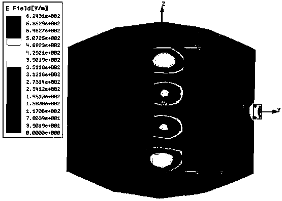
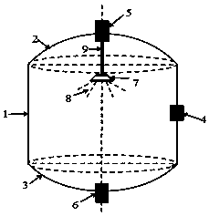
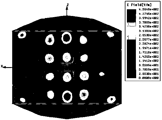
[0030] Embodiment 1: as Figure 1-3As shown, a capsule cylindrical microwave flash device for heavy metal wastewater treatment includes a resonant cavity main body, a microwave feed port 4, a waste liquid inlet 5, a waste liquid outlet 6, a flash nozzle 7, and a waste liquid delivery pipeline 9; The main body of the resonant cavity is composed of an upper metal cavity 2, a cylindrical waveguide 1, and a lower metal cavity 3; the upper metal cavity 2 and the lower metal cavity 3 are located at the upper and lower ends of the cylindrical waveguide 1; The side is closed and fastened with the main body of the resonant cavity. The waste liquid inlet 5 and the waste liquid outlet 6 are arranged on the top and bottom of the main body of the resonant cavity and communicate with the inner cavity. The flash nozzle 7 is set in the main body of the resonant cavity. 9 Connect the waste liquid inlet 5 and the flash nozzle 7.

[0031] The main body of the resonant cavity is capsule cylindri...

Embodiment 2

[0034] Embodiment 2: as Figure 1-3 As shown, a capsule cylindrical microwave flash device for heavy metal wastewater treatment includes a resonant cavity main body, a microwave feed port 4, a waste liquid inlet 5, a waste liquid outlet 6, a flash nozzle 7, and a waste liquid delivery pipeline 9; The main body of the resonant cavity is composed of an upper metal cavity 2, a cylindrical waveguide 1, and a lower metal cavity 3; the upper metal cavity 2 and the lower metal cavity 3 are located at the upper and lower ends of the cylindrical waveguide 1; The side is closed and fastened with the main body of the resonant cavity. The waste liquid inlet 5 and the waste liquid outlet 6 are arranged on the top and bottom of the main body of the resonant cavity and communicate with the inner cavity. The flash nozzle 7 is set in the main body of the resonant cavity. 9 Connect the waste liquid inlet 5 and the flash nozzle 7.

[0035] The main body of the resonant cavity is capsule cylindr...

Embodiment 3

[0041] Embodiment 3: as Figure 1-3 As shown, a capsule cylindrical microwave flash device for heavy metal wastewater treatment includes a resonant cavity main body, a microwave feed port 4, a waste liquid inlet 5, a waste liquid outlet 6, a flash nozzle 7, and a waste liquid delivery pipeline 9; The main body of the resonant cavity is composed of an upper metal cavity 2, a cylindrical waveguide 1, and a lower metal cavity 3; the upper metal cavity 2 and the lower metal cavity 3 are located at the upper and lower ends of the cylindrical waveguide 1; The side is closed and fastened with the main body of the resonant cavity. The waste liquid inlet 5 and the waste liquid outlet 6 are arranged on the top and bottom of the main body of the resonant cavity and communicate with the inner cavity. The flash nozzle 7 is set in the main body of the resonant cavity. 9 Connect the waste liquid inlet 5 and the flash nozzle 7.

[0042] The main body of the resonant cavity is capsule cylindr...


PUM


Abstract

The invention relates to a capsule cylindrical microwave flash evaporation device used for heavy metal wastewater treatment and belongs to the technical field of heavy metal wastewater evaporation treatment. The device comprises a resonance cavity body, a microwave feed inlet, a waste liquid inlet, a waste liquid outlet, a flash evaporation nozzle and a waste liquid conveying pipeline. The resonance cavity body is composed of an upper metal cavity, a cylindrical waveguide pipe and a lower metal cavity. The upper metal cavity and the lower metal cavity are located at the upper end and the lower end of the cylindrical waveguide pipe. The microwave feed inlet is formed in the side face of the cylindrical waveguide pipe and is fixedly connected with the resonance cavity body in a sealed mode. The waste liquid inlet and the waste liquid outlet are formed in the top and the bottom of the resonance cavity body and are communicated with an inner cavity of the resonance cavity body. The flash evaporation nozzle is disposed in the resonance cavity body, and the waste liquid conveying pipeline is connected with the waste liquid inlet and the flash evaporation nozzle. The device has the advantages that the structure is simple, cost is low, coupling efficiency between the feed inlet and the flash evaporation cavity is high, the volume of the cavity is large, the concentration ratio of an area with large field strength is high, the Q value of the cavity is high, and microwave flash evaporation is environmentally friendly, quick, efficient and capable of saving energy.

Description

technical field [0001] The invention relates to a capsule cylindrical microwave flash evaporation device for heavy metal wastewater treatment, belonging to the technical field of evaporation treatment of heavy metal wastewater. Background technique [0002] With the rapid development of my country's modern industry, the problem of heavy metal pollution in industrial wastewater has become increasingly serious. How to effectively control heavy metal pollution, efficiently treat these heavy metal wastewater, and make it resource has become a common concern of people. Evaporation is one of the effective ways to treat wastewater containing heavy metal ions. As one of the important chemical unit operations, evaporation is a method of heating to partially vaporize the water or volatile solvent in the solution in a boiling state. Therefore, the evaporation process is a process of heat transfer. For metallurgy and chemical industry, the heat required for evaporation mainly comes fr...

Claims


Application Information

Patent Timeline
Patent Type & Authority Patents(China)
IPC IPC(8): C02F1/06C02F1/30
CPCC02F1/06C02F1/302C02F2201/002
Inventor 陈华巨少华张瑾郭战永樊则宾
Owner 熠谱(上海)半导体制造有限公司
Why Eureka
Try Eureka