Layered array method and device for depositing metal nanoparticles on fiber end face

A technology of metal nanoparticles and fiber end face, applied in the field of nano-optics, can solve the problems of high cost, poor controllability, difficult mass production, etc., and achieve the effect of low price and strong controllability

Inactive Publication Date: 2016-04-20
HUAZHONG UNIV OF SCI & TECH
View PDF4 Cites 3 Cited by
  • Summary
  • Abstract
  • Description
  • Claims
  • Application Information

AI Technical Summary

Problems solved by technology

Periodic nanostructures can maintain high repeatability. It is often difficult to deposit this type of structure on the optical fiber. Generally, this structure is based on the method of electron beams to prepare metal nanoantennas on the end of the optical fiber. The repeatability Higher, but the cost is high and the preparation process is very complicated
People use the method of molecular self-assembly to form a monomolecular layer by silanizing the surface of the optical fiber, and then immerse the end face of the optical fiber in gold-silver nano-sol to form a layer of metal nanoparticles on the surface. This method is simple. But the controllability is not good, the arrangement is irregular
Another method is called photoreduction method deposition. By coupling laser light into one end of the optical fiber, the other end is immersed in a silver ion solution containing a reducing agent. Under the action of light, the silver ions will be reduced to silver nanoparticles, which will be deposited on the end surface of the optical fiber after emission. A certain light field distribution is formed, and silver nanoparticles will be produced at the corresponding places. By controlling the exit spot shape of the optical fiber, the controllable preparation of gold and silver nanoparticles can be realized. This method is simple and efficient, but it is difficult to achieve mass production.

Method used


Image

  • Layered array method and device for depositing metal nanoparticles on fiber end face

Examples


Embodiment Construction

[0022] In order to make the object, technical solution and advantages of the present invention clearer, the present invention will be further described in detail below in conjunction with the accompanying drawings and embodiments. It should be understood that the specific embodiments described here are only used to explain the present invention, not to limit the present invention. In addition, the technical features involved in the various embodiments of the present invention described below can be combined with each other as long as they do not constitute a conflict with each other.

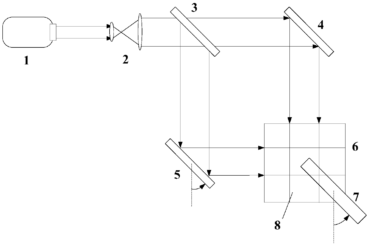
[0023] In the present invention, by building a set of interference light path based on double beams, two beams of coherent light can be overlapped in the silver ion solution, and the end face of the optical fiber is placed in the overlapping area. Nanostructured silver nanoparticle arrays.

[0024] Such as figure 1 As shown, the device for depositing a layered array of metal nanoparticles on t...


PUM

PropertyMeasurementUnit
quality scoreaaaaaaaaaa

Abstract

The invention discloses a layered array method and device for depositing metal nanoparticles on a fiber end face. The method comprises the steps as follows: pretreatment of the fiber end face is carried out by using a piranha solution and a silane solution, and a monomolecular layer which can be combined with the metal nanoparticles firmly and easily is formed on the fiber end face; a reducing solution containing metal salt and a reducing agent is prepared, and two beams of laser are enabled to intersect and generate interference; and the fiber end face is placed in the intersecting area of the two beams of the laser in the reducing solution, and the periodic metal nanoparticle layered array corresponding to interfering light spots is formed on the fiber end face. Light for a deposition reaction is formed by interference generated by two beams of laser; the influence of optical fiber on reaction light is avoided; and the controllability of the silver nanoparticle deposition on the fiber end face is enabled to be higher.

Description

technical field [0001] The invention belongs to the technical field of nano optics, and more specifically relates to a method and a device for depositing a layered array of metal nanoparticles on the end face of an optical fiber. Background technique [0002] As a special optical waveguide, optical fiber plays an important role in modern society. With the characteristics of flexibility, long-distance transmission, and resistance to electromagnetic interference, it has been widely used in the field of sensing in recent years, especially with nano-optical structures. After the structure is deposited on the fiber end face, it plays a very important role in the field of surface plasmon resonance sensor and surface enhanced Raman spectroscopy measurement. For sensing technology in the field of biochemistry, factors such as repeatability, low cost, and large batches need to be considered as sensor devices. Periodic nanostructures can maintain high repeatability. It is often diff...

Claims


Application Information

Patent Timeline
Patent Type & Authority Applications(China)
IPC IPC(8): C23C18/14B22F9/30
CPCC23C18/14B22F9/30
Inventor 汤自荣朱桅史铁林黄捷周腾远
Owner HUAZHONG UNIV OF SCI & TECH
Why Eureka
Try Eureka