Vacuum sewage collecting and treating system

A technology of vacuum collection and treatment system, applied in water/sewage treatment, biological water/sewage treatment, water/sewage multi-stage treatment, etc. issues such as increased costs

Active Publication Date: 2016-04-20
清环拓达(苏州)环境科技有限公司
View PDF6 Cites 22 Cited by
  • Summary
  • Abstract
  • Description
  • Claims
  • Application Information

AI Technical Summary

Problems solved by technology

[0005] 1. It is easily restricted by the terrain, not suitable for places with many undulations, shallow rock layers or unstable soil, not suitable for residential areas with high water levels in the surrounding waters or areas where pits should not be excavated too deep;
[0006] 2. It cannot be flexibly coordinated with other professional pipelines as a whole, and it is not suitable for residents to live in scattered areas or places where other municipal and other public facilities have been buried underground;
[0007] 3. Larger slopes and buried depths ar

Method used


Image

  • Vacuum sewage collecting and treating system
  • Vacuum sewage collecting and treating system
  • Vacuum sewage collecting and treating system

Examples


Embodiment 1

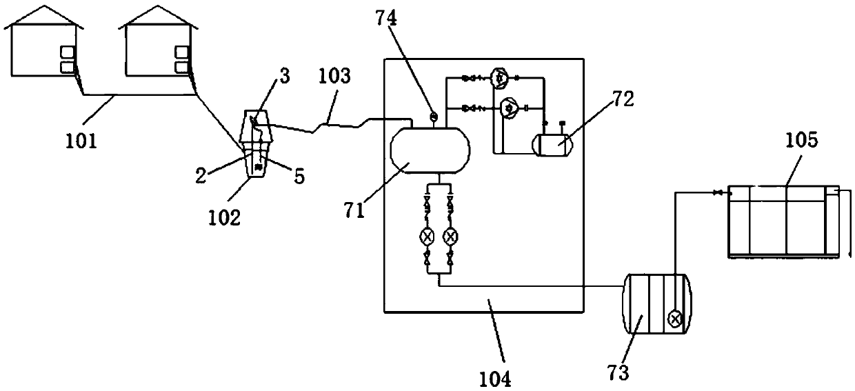
[0056] see figure 1 , a sewage vacuum collection and treatment system, including a sewage confluence pipeline 101, a vacuum collection well 102, a vacuum delivery pipeline 103, a vacuum pump station 104 and a sewage processor 105.

[0057] Wherein, the sewage confluence pipeline 101 guides the sewage discharged from the user end to the vacuum collection well 102 . One vacuum collection well 102 can correspond to several sewage confluence pipelines 101 leading from the user end. One end of the vacuum delivery pipeline 103 is drawn from the vacuum collection well 102 , and the other end extends to the vacuum sewage storage tank 71 of the vacuum pumping station 104 .

[0058] The vacuum pump station 104 includes a vacuum sewage storage tank 71, a vacuum pump 72, a sewage delivery pump 73, an electrical control system and a generator. The vacuum sewage storage tank 71 is used to collect sewage from the vacuum collection well, and a vacuum pump 72 and a sewage delivery pump 73 ar...

Embodiment 2

[0078] see Figure 12 , the vacuum collection well 12 includes a composting well 10 connected to the sewage confluence line 101, and the valve well 1 described in Embodiment 1. This valve well 1 communicates with the retting fertilizer well 10. The bottoms of the retting well 10 and the valve well 1 are provided with a sewage communication port 20 and a filter grid 21 arranged on the sewage communication port 20 near the retting well side, and a grid tie rod 22 is also fixed on the filter grid 21 . The above-mentioned retting well 10 and the valve well 1 are all formed by pouring reinforced concrete. All the other are with embodiment 1.

[0079]Aiming at the problem that the existing vacuum well does not have a retting function, a retting well connected to the valve well is set between the valve well and the user end, and the user sewage first flows into the retting well through a short-distance gravity pipeline for decomposition and fermentation. The larger floating matter...


PUM


Abstract

The invention discloses a vacuum sewage collecting and treating system. The vacuum sewage collecting and treating system comprises a sewage gathering pipeline, a vacuum collection well, a vacuum conveying pipeline, a vacuum pump station and a sewage treating device, wherein the sewage enters the vacuum collection well through the sewage gathering pipeline; when the sewage collected in the well reaches a certain amount, the sewage enters the vacuum pump station along the vacuum conveying pipeline; when the liquid level of the sewage in a vacuum sewage storage tank reaches a predetermined liquid level, the sewage conveying pump is started and is used for conveying the sewage to the sewage treating device to purify the sewage. Through the vacuum sewage collecting and treating system, the domestic sewage collection method is changed from the conventional gravity collection into vacuum collection; the sewage treatment is charged from a manner of discharging the sewage into a sewage pipe net and carrying out centralized treatment on the sewage to a process of carrying out on-site treatment by using a small integrated membrane treatment device; collection and treatment are integrated to a complete set of system; the system is not limited by basic supporting facilities and is not required to relay on urban drainage facilities; the system is integrated with the ecological environmental protection technology with efficient collection and efficient treatment functions and is especially suitable for regions such as small towns and countries and the like in which sewage treatment plants are unsuitably built.

Description

technical field [0001] The invention belongs to the field of sewage collection and treatment, and in particular relates to an integrated and miniaturized system that uses vacuum technology to realize sewage collection and treatment. Background technique [0002] In cities and densely populated areas, gravity pipelines are often used to collect sewage. The sewage in buildings flows into outdoor inspection wells. The sewage pipelines are laid according to a certain slope. The sewage is transported along the pipeline to the sewage lifting well by gravity, and then pumped The station is upgraded to the sewage treatment facility. In order to prevent the sewage in the pipeline from clogging, it is often necessary to adopt a certain slope when laying the pipeline. Therefore, the sewage pipeline is generally buried relatively deep, and the project investment is high. [0003] With the acceleration of my country's urbanization process, the pressure of sewage treatment in small towns ...

Claims


Application Information

Patent Timeline
IPC IPC(8): E03F1/00E03F11/00E03F5/22E03F5/14C02F9/14
CPCC02F1/001C02F1/44C02F3/02C02F3/1268C02F3/30C02F9/00C02F2103/001E03F1/006E03F5/14E03F5/22E03F11/00Y02A20/208
Inventor 邓永峰王福清宋容华
Owner 清环拓达(苏州)环境科技有限公司
Why Eureka
Try Eureka