An Immersed Ceramic Resistance Internal Heating Device
A ceramic resistance and internal heating technology, applied in electric heating devices, ohmic resistance heating, electric furnace heating, etc., can solve problems such as limiting the popularization and application of internal heating technology, molten liquid charging or liquid level jumping, and internal heater failure, etc. Suppression of interfacial discharge, remarkable melt infiltration, and long service life
- Summary
- Abstract
- Description
- Claims
- Application Information
AI Technical Summary
Problems solved by technology
Method used
Image
Examples
Embodiment 1
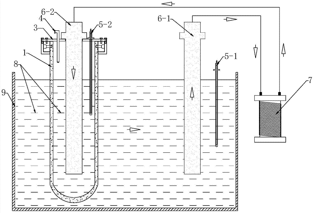
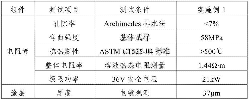
[0032] Such as figure 1 As shown, the immersion-type ceramic resistance internal heating device of this embodiment includes a transformer 7 and a molten pool 9, and a resistance tube 1 and a first electrode 6-1 are inserted in the molten pool 9, and the upper end of the resistance tube 1 is opened at the lower end Closed, the melting pool 9 and the resistance tube 1 are filled with molten metal 8, the resistance tube 1 is inserted with a second electrode 6-2, the first electrode 6-1, and the second electrode 6 The lower part of -2 is immersed in the molten metal 8, and the upper parts of the first electrode 6-1 and the second electrode 6-2 are connected to the transformer 7 through wires, and carbonization is deposited on the inner wall and the outer wall of the resistance tube 1. Silicon coating.
[0033] Such as figure 1 As shown, the top of the resistance tube 1 is provided with an insulating cover plate 3, and the insulating cover plate 3 is provided with a vent pipe 4 f...
Embodiment 2
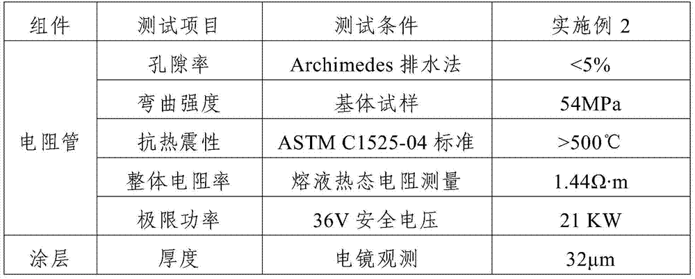
[0051] The immersion-type ceramic resistance internal heating device of this embodiment is the same as that of Embodiment 1, except that the silicon carbide coating and the preparation method of the resistance tube 1 are different. Wherein, the preparation method of the silicon carbide coating is: placing the resistance tube 1 in a chemical vapor deposition furnace, using CH 3 SiCl 3 As a raw material, hydrogen is used as a carrier gas, and argon is used as a diluent gas. The hydrogen flow rate is 400mL / min, the argon flow rate is 150mL / min, and the temperature is 1000°C. A silicon carbide coating is obtained. The preparation method of the resistance tube 1 comprises the following steps:
[0052] Step 1. Weigh the following raw materials in mass percentage: SiC 50%, graphite 33%, Y 2 o 3 3%;Al 2 o 3 2%; Ni 4%; Mo 4%, TiC 4%; all raw materials are powder, graphite is preferably nano-graphite powder;
[0053] Step 2. Mix the raw materials weighed in step 1 evenly by ball ...
Embodiment 3
[0063] The immersion-type ceramic resistance internal heating device of this embodiment is the same as that of Embodiment 1, except that the silicon carbide coating and the preparation method of the resistance tube 1 are different. Wherein, the preparation method of the silicon carbide coating is: placing the resistance tube 1 in a chemical vapor deposition furnace, using CH 3 SiCl 3 As a raw material, hydrogen is used as a carrier gas, and argon is used as a diluent gas. The hydrogen flow rate is 200mL / min, the argon flow rate is 100mL / min, and the temperature is 1200°C. A silicon carbide coating is obtained. The preparation method of the resistance tube 1 comprises the following steps:
[0064] Step 1. Weigh the following raw materials in mass percentage: SiC 60%, graphite 28%, Y 2 o 3 1.5%;Al 2 o 3 1.5%; Ni 3%; Mo 3%, TiC 3%; all raw materials are powder, graphite is preferably nano-graphite powder;
[0065] Step 2. Mix the raw materials weighed in step 1 evenly by b...
PUM
| Property | Measurement | Unit |
|---|---|---|
| thickness | aaaaa | aaaaa |
| flexural strength | aaaaa | aaaaa |
| thickness | aaaaa | aaaaa |
Abstract
Description
Claims
Application Information
 - R&D
- Intellectual Property
- Life Sciences
- Materials
- Tech Scout
- Unparalleled Data Quality
- Higher Quality Content
- 60% Fewer Hallucinations
Browse by: Latest US Patents, China's latest patents, Technical Efficacy Thesaurus, Application Domain, Technology Topic, Popular Technical Reports.
© 2025 PatSnap. All rights reserved.Legal|Privacy policy|Modern Slavery Act Transparency Statement|Sitemap|About US| Contact US: help@patsnap.com


