Flue gas waste heat utilization system for annealing furnace

A flue gas waste heat and annealing furnace technology, which is applied to furnaces, furnace materials, waste heat treatment, etc., can solve the problems of increasing the load of induced draft fans, wasting flue gas heat energy, and wasting heat energy, so as to reduce the exhaust gas temperature, prevent environmental pollution, and improve The effect of the recycling effect

Inactive Publication Date: 2016-04-20
NINGBO HEXIE ENERGY CONSERVATION
View PDF0 Cites 4 Cited by
  • Summary
  • Abstract
  • Description
  • Claims
  • Application Information

AI Technical Summary

Problems solved by technology

[0002] With the advancement of social progress and the advancement of energy conservation and emission reduction policies, various waste heat recovery equipment and systems have been continuously applied to effective energy-saving means. Although the annealing furnace flue gas waste heat recovery system has gradually matured and has been widely used It is used in actual production; and because the flue gas of the annealing furnace passes through the heat exchanger for one heat exchange, the temperature of the combustion exhaust gas of the annealing furnace has dropped to about 350°C. Due to the low temperature of the flue gas, the current part of the flue gas Most of the treatment methods are: or directly discharge, which will lead to a serious waste of heat energy; or mix a certain proportion of air in the flue gas, reduce its temperature to about 250 ℃ and discharge, and there is also a lot of waste in this way. The thermal energy of the flue gas increases the problem of the load of the induced draft fan.

Method used


Image

  • Flue gas waste heat utilization system for annealing furnace

Examples


Embodiment Construction

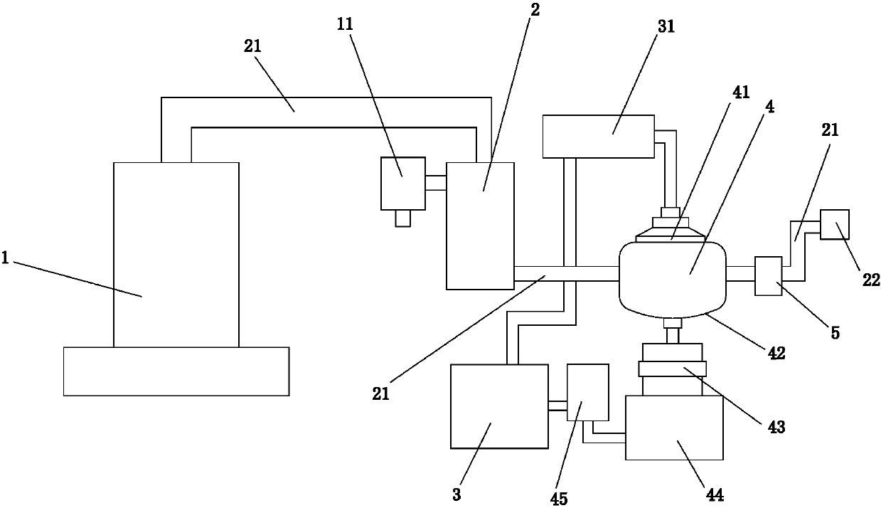
[0010] Below in conjunction with accompanying drawing and specific embodiment the present invention will be described in further detail: figure 1 As shown, the annealing furnace flue gas waste heat utilization system includes an annealing furnace 1, a heat exchanger 2 connected with the annealing furnace 1, a flue 21 and an exhaust chimney 22, and the heat exchanger 2 is provided with a dust removal function Air intake part 11, a cooling furnace 4 is arranged between the chimney 22 and the heat exchanger 2, a water spray pump 32 is connected above the cooling furnace 4, and a water tank 3 is connected to the water spray pump 32. The cooling furnace 4, a cooling water cooling device 44 is connected below, and a filtering device 43 is arranged between the cooling furnace 4 and the cooling water cooling device 44. The cooling water cooling device 44 is also connected with a water pump 45, and the water pump 45 The cooled water in the cooling water cooling device 44 is input into ...


PUM


Abstract

The invention discloses a flue gas waste heat utilization system for an annealing furnace. The flue gas waste heat utilization system for the annealing furnace comprises the annealing furnace, a heat exchanger connected with the annealing furnace, a flue and a discharge chimney, wherein an intake part with a dust removal function is arranged on the heat exchanger; a cooling furnace is arranged between the chimney and the heat exchanger; a water jet pump is connected above the cooling furnace; the water jet pump is connected with a water tank; a cooling water cooling device is connected below the cooling furnace; a filter device is arranged between the cooling furnace and the cooling water cooling device; a water suction pump is further connected to the cooling water cooling device; and the water suction pump is used for inputting water cooled in the cooling water cooling device into the water tank. Compared with the prior art, the flue gas waste heat utilization system for the annealing furnace, which is disclosed by the invention, is capable of effectively lowering a flue gas exhaust temperature of the annealing furnace, improving a recycling effect for flue gas heat energy, and removing dust and other impurities in a flue gas, thus preventing environmental pollution.

Description

technical field [0001] The invention relates to a flue gas waste heat recovery system, in particular to an annealing furnace flue gas waste heat recovery system. Background technique [0002] With the advancement of social progress and the advancement of energy conservation and emission reduction policies, various waste heat recovery equipment and systems have been continuously applied to effective energy-saving means. Although the annealing furnace flue gas waste heat recovery system has gradually matured and has been widely used It is used in actual production; and because the flue gas of the annealing furnace passes through the heat exchanger for one heat exchange, the temperature of the combustion exhaust gas of the annealing furnace has dropped to about 350°C. Due to the low temperature of the flue gas, the current part of the flue gas Most of the treatment methods are: or directly discharge, which will lead to a serious waste of heat energy; or mix a certain proportion...

Claims


Application Information

Patent Timeline
Patent Type & Authority Applications(China)
IPC IPC(8): F27D17/00
CPCF27D17/004F27M2003/01Y02P10/25
Inventor 沈锋郭莎莎
Owner NINGBO HEXIE ENERGY CONSERVATION
Why Eureka
Try Eureka