
An intelligent dehumidification system for an electrical terminal box

An electrical terminal and intelligent technology, applied in the direction of control/regulation system, humidity control, non-electric variable control, etc., can solve the problems of reducing condensation, aging, and unable to solve condensation problems, and achieve the effect of reducing workload

Active Publication Date: 2017-08-22
HANGZHOU ICEWAY ELECTRIC SCI & TECH CO LTD
View PDF4 Cites 0 Cited by
  • Summary
  • Abstract
  • Description
  • Claims
  • Application Information

AI Technical Summary

Problems solved by technology

The actual dehumidification effect of the electrical equipment inside the cabinet is not good. Electric heating actually increases the air flow and reduces condensation to a certain extent, so it cannot dehumidify at all; Circulation, only local dehumidification in the cabinet
After opening the cabinet door, it is found that there is condensed water on the cabinet door or the electrical equipment at the position blocked by the electrical equipment or far away from the installation position of the conventional electronic dehumidifier, indicating that this dehumidification method cannot meet the requirements of the electrical equipment in the cabinet. Basic requirements for safe operation
The dehumidification of various indoor and outdoor electrical equipment cabinets adopts the method of installing electric heating in the cabinet with natural ventilation or forced ventilation, and sometimes the second, third and fourth guide wires around the electric heater are prematurely aged or burned , and because the air inside and outside the cabinet communicates, frequent heating and dehumidification not only has poor dehumidification effect, but also consumes a lot of power.
[0004] There is also a drainage type dehumidification method, but it has not been widely used and promoted. This dehumidification method is to create a condensation surface through a liquefaction device, so that the water vapor in the air becomes liquid water on the condensation surface, and then discharged out of the box through a specific structure. , so the drainage and dehumidification method still cannot solve the condensation problem that has formed in the cabinet
[0005] A variety of electrical cabinets in the power system need to be placed outdoors. Due to the level of processing technology and the characteristics of use, it is difficult for the electrical cabinets to be completely airtight, resulting in the accumulation of hot and humid air in the atmosphere. When the temperature drops suddenly, the inside of the electrical cabinet will Condensation occurs, causing problems such as short circuit and corrosion; therefore, the effective dehumidification of electrical cabinets including terminal boxes has always been an important task in the field of substation operation. How to solve the problem of condensation in the electrical cabinet and prevent further condensation, It is a technical problem to be solved urgently in this field

Method used


Image

  • An intelligent dehumidification system for an electrical terminal box
  • An intelligent dehumidification system for an electrical terminal box
  • An intelligent dehumidification system for an electrical terminal box

Examples


Embodiment Construction

[0040] In order to describe the present invention more specifically, the technical solutions of the present invention will be described in detail below in conjunction with the accompanying drawings and specific embodiments.

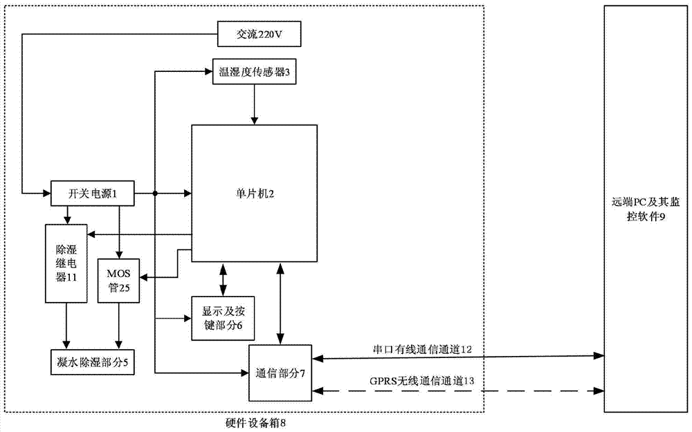
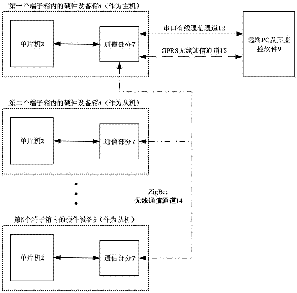
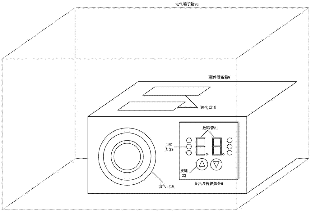
[0041] Such as figure 1 As shown, the electrical terminal box intelligent dehumidification system of the present invention is composed of a remote PC and its monitoring software 9 and a hardware equipment box 8 installed in a local electrical terminal box 20 . Such as image 3 As shown, the hardware equipment box 8 is placed in the electrical terminal box 20, and its appearance is a rectangular box. The hardware equipment box 8 has an air inlet 15 and an air outlet 16. The equipment box includes a switching power supply 1, a temperature and humidity sensor 3, a condensation dehumidification part 5, a display and button part 6, and a communication part 7, all of which are controlled by a single-chip microcomputer 2.

[0042] The single-chip microcomputer...


PUM


Abstract

The invention discloses an intelligent dehumidifying system of an electrical terminal box. The intelligent dehumidifying system comprises a hardware equipment box which is installed in the electrical terminal box and a far-end upper computer which communicates with the hardware equipment box. The hardware equipment box comprises a box body, and a switching power supply, a single-chip microcomputer, a temperature and humidity sensor, a water condensing and dehumidifying mechanism and a communication module which are arranged in the box body. The working characteristics of semiconductor refrigeration sheets are utilized, an extremely cold surface is formed on condensation sheets for condensation and dehumidification, and a high temperature surface is formed on heat-radiating fins to heat the previously condensed air again so that temperature in the electrical terminal box is enabled not to sharply fluctuate, and air can be cyclically condensed on the condensation sheets; temperature near an air inlet is low and temperature near an air outlet is high due to the installation position of the condensation sheets and the heat-radiating fins, and the position of the air inlet relative to the air outlet is higher so that air convection is facilitated by the design; and air circulation can be formed in a forced way by the effect of fans so that the common condensation problem in the terminal box, a switch cabinet and other electrical cabinets can be fundamentally solved.

Description

technical field [0001] The invention belongs to the technical field of dehumidification of electrical equipment, and in particular relates to an intelligent dehumidification system for an electrical terminal box. Background technique [0002] With the rapid development of urban construction, electrical equipment is widely used, and electric cabinets for installing and protecting these electrical equipment are widely used. In order to prevent electrical equipment from malfunctioning during operation, a dehumidification device will be installed in the electrical cabinet to control its humidity. [0003] At present, the dehumidification in the electrical equipment cabinet often adopts a large conventional electronic dehumidifier with electric heating in the cabinet and natural ventilation, or forced ventilation. The actual dehumidification effect of the electrical equipment inside the cabinet is not good. Electric heating actually increases the air flow and reduces condensatio...

Claims


Application Information

Patent Timeline
Patent Type & Authority Patents(China)
IPC IPC(8): G05D22/02
CPCG05D22/02
Inventor 董建洋
Owner HANGZHOU ICEWAY ELECTRIC SCI & TECH CO LTD
Learn More