Low-voltage circuit dynamic reactive power compensation device and low-voltage circuit reactive power compensation method

A low-voltage circuit and compensation device technology, which is applied in reactive power compensation, circuit devices, reactive power adjustment/elimination/compensation, etc., can solve problems such as reducing the service life of capacitors, switching oscillations, reactive power transfer, etc. Efficiency and compensation accuracy, avoiding wiring errors, reasonable switching design effects

Inactive Publication Date: 2016-04-20
BENGBU HUITAI ELECTRIC AUTOMATION
View PDF5 Cites 3 Cited by
  • Summary
  • Abstract
  • Description
  • Claims
  • Application Information

AI Technical Summary

Problems solved by technology

[0004] 1. For the reactive power required in the circuit, the existing compensation device puts a group of capacitors into the circuit, and the output reactive power compensation may exceed the upper limit of the normal demand due to the unreasonable setting of the capacitor capacity and the upper and lower limits of the power factor value; when the capacitor is removed, the fixed power will be lower than the lower limit of the normal demand, which will cause the compensation device to switch the capacitor bank repeatedly, reduce the service life of the capacitor and the switching switch, and affect the stability of the system. make an impact
[0005] 2. The sampling method of the existing compensation device is unreasonable, resulting in reactive power reverse. Some compensation devices only sample the current signal or voltage signal of one phase. When the three-phase load is unbalanced, the reactive power will be detected incorrectly, resulting in one phase or Two-phase overcompensation or undercompensation
[0006] 3. The compensation speed of the existing compensation device is slow and the accuracy is poor. It is difficult for the controller to sample the three-phase voltage and current signals to monitor the reactive power in real time.
[0007] 4. The switching switch design of the existing compensation device is unreasonable
When the contactor is used as a switching switch, an inrush current will be generated to cause voltage fluctuations in the grid, which may easily cause damage to the contactor and reduce the service life of the capacitor
[0008] 5. The switching method of the existing compensation device is unreasonable. It mainly uses sequential switching and cyclic switching, which not only affects the service life of switching switches and capacitors, but also causes switching oscillations and affects the compensation effect

Method used


Image

  • Low-voltage circuit dynamic reactive power compensation device and low-voltage circuit reactive power compensation method
  • Low-voltage circuit dynamic reactive power compensation device and low-voltage circuit reactive power compensation method
  • Low-voltage circuit dynamic reactive power compensation device and low-voltage circuit reactive power compensation method

Examples


Embodiment 1

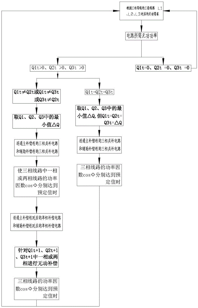
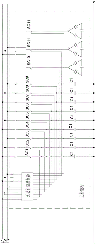
[0044] Such as figure 1 shown

[0045] This device includes a main compensation cabinet, an auxiliary compensation cabinet and an aviation socket.

[0046] The main compensation cabinet includes a reactive power compensation controller, nine single-phase compensation circuits and three three-phase compensation circuits.

[0047] The nine single-phase compensation circuits are the first single-phase main compensation circuit, the second single-phase main compensation circuit, the third single-phase main compensation circuit, the fourth single-phase main compensation circuit, the fifth single-phase main compensation circuit, the sixth Single-phase main compensation circuit, seventh single-phase main compensation circuit, eighth single-phase main compensation circuit and ninth single-phase main compensation circuit. Capacitor, taking the first single-phase main compensation circuit as an example, the first single-phase main compensation circuit is provided with a single-phase s...

Embodiment 2

[0069] The difference between this embodiment and Embodiment 1 is that the low-voltage circuit dynamic reactive power compensation device in this embodiment has only the main compensation cabinet, but no auxiliary compensation cabinet. The method and embodiment of the low-voltage circuit dynamic reactive power compensation device in this embodiment One is the same.

[0070] It can be seen that the auxiliary compensation cabinet can be flexibly selected according to the environment of use and the demand for reactive power compensation.

[0071] Compared with ordinary single-chip microcomputer chips, the above-mentioned reactive power compensation controller has the advantages of fast processing speed, accurate data processing, and large storage capacity.

[0072] The reactive power compensation controller measures and calculates the three-phase voltage, current, active power, reactive power, etc., which can improve the sampling rate and data accuracy.


PUM


Abstract

The invention presents a low-voltage circuit dynamic reactive power compensation device. A single-phase compensation circuit of a main compensation cabinet is connected with a three-phase live wire and a null line; a three-phase compensation circuit is provided with a three-phase switching switch and a capacitor bank, and the three-phase switching switch controls connection of the capacitor bank and a three-phase bus; a reactive power compensation controller controls a single-phase switching switch and the three-phase switching switch to be switched on or off. By means of the device, split-phase or three-phase circuit dynamic compensation is performed on a reactive power requirement in a circuit. The invention further provides a method for performing reactive power compensation on the low-voltage circuit through the device. The method includes the following steps that a reactive power requirement of a three-phase circuit at the moment t is monitored; when three phases are all equal to zero, the device is not started; when the three phases are larger than zero and are equal, the controller performs control for compensation; when the three phases are required to be larger than zero and are not equal, the controller firstly controls the three-phase switching switch to perform compensation, and then single-phase compensation is performed on a one-phase circuit or a two-phase circuit in the three-phase circuit; when one phase or two phases are larger than zero, the controller performs split compensation on a signal phase.

Description

technical field [0001] The invention relates to a dynamic reactive compensation device in a low-voltage circuit. [0002] The invention also relates to a method for reactive power compensation of a low-voltage circuit. Background technique [0003] Reactive power compensation, referred to as reactive power compensation, plays a role in improving the power factor of the power grid in the power supply system, reducing the loss of power supply transformers and transmission lines, improving power supply efficiency, and improving the power supply environment. Reasonable selection of compensation devices can minimize the loss of the power grid and improve the quality of the power grid. However, the current compensation device has the following disadvantages: [0004] 1. For the reactive power required in the circuit, the existing compensation device puts a group of capacitors into the circuit, and the output reactive power compensation may exceed the upper limit of the normal de...

Claims


Application Information

Patent Timeline
Patent Type & Authority Applications(China)
IPC IPC(8): H02J3/18H02J3/24
CPCY02E40/30H02J3/1807H02J3/24
Inventor 陈克乐王永道王灿
Owner BENGBU HUITAI ELECTRIC AUTOMATION
Why Eureka
Try Eureka