Optical fiber ribbon curing equipment

A technology for curing equipment and optical fiber ribbons, which can be used in pretreatment surfaces, coatings, devices for coating liquids on surfaces, etc. Curing quality and other issues to achieve the effect of improving work efficiency, reducing energy consumption, and improving curing uniformity

Active Publication Date: 2016-04-27
YANGTZE OPTICAL FIBRE & CABLE CO LTD
View PDF4 Cites 8 Cited by
  • Summary
  • Abstract
  • Description
  • Claims
  • Application Information

AI Technical Summary

Problems solved by technology

Mercury lamps have the disadvantage of requiring considerable power to produce UV radiation of sufficient intensity
For example, curing a single-coated fiber (such as polymer coating) may require a total power consumption of 50kW
Another disadvantage of mercury lamps is that a large amount of energy used to light mercury lamps is emitted as heat instead of ultraviolet rays, which means that mercury lamps have a relatively low energy utilization rate
Generally, UV radiation with a wavelength between 300 and 400 nanometers can be used for curing, so most of the electromagnetic radiation generated by mercury lamps is wasted
In addition, curing the surface of the optical fiber ribbon with a mercury lamp is limited to single or double lamp irradiation, and the optical fiber ribbon is a tetrahedron, so it is difficult to irradiate the four sides uniformly, thus affecting the coating curing quality of the optical fiber ribbon

Method used


Image

  • Optical fiber ribbon curing equipment
  • Optical fiber ribbon curing equipment
  • Optical fiber ribbon curing equipment

Examples


Embodiment Construction

[0018] The embodiments of the present invention will be further described below in conjunction with the accompanying drawings.

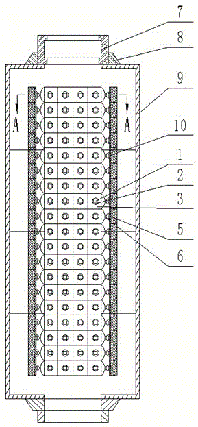
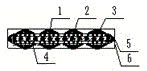
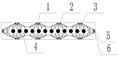
[0019] Including a cylindrical base 9, the cross-section of the cylindrical base is rectangular, the upper and lower ends of the cylindrical base are respectively provided with an optical fiber ribbon inlet and an optical fiber ribbon outlet, and the optical fiber ribbon inlet at the upper end of the cylindrical base is connected by The seat 8 is equipped with an optical fiber ribbon and has a mold 7 . During the production process of optical fiber ribbon, the optical fiber ribbon is bonded and coated by resin material in the mold, and then passes through the inner cavity of the cylindrical base of the curing equipment along the curing axis. In the inner cavity of the cylindrical base along the direction of travel of the optical fiber ribbon, UVLED light source modules 1 are respectively installed on the front and back sides of the corresponding opti...


PUM


Abstract

The invention discloses optical fiber ribbon curing equipment. The optical fiber ribbon curing equipment comprises a barrel-shaped base, and an optical fiber ribbon inlet and an optical fiber ribbon outlet are respectively formed in the upper end and the lower end of the barrel-shaped base. The optical fiber ribbon curing equipment is characterized in that UVLED light source modules are arranged in an inner cavity of the barrel-shaped base in the optical fiber ribbon passing direction and respectively correspond to the front surface and the rear surface of an optical fiber ribbon; luminous surfaces of the UVLED light source modules face inwards correspondingly; and a hemispherical diffuser and a hemispherical lens light uniformizing film are arranged in the front of each UVLED light source module. The UVLED light source modules serve as UV radiation sources, so that energy consumption of the equipment can be reduced remarkably, and the purposes of energy conservation and environmental friendliness are achieved; the UVLED light source modules are respectively arranged on the front surface, reverse surface and two sides of the optical fiber ribbon, so that radiation of ultraviolet light is even; and the surface of the optical fiber ribbon is illuminated evenly so that the equipment has high curing efficiency and good curing uniformity, curing time is shortened, work efficiency of optical fiber ribbon combination is improved, and curing quality of coatings is also improved.

Description

technical field [0001] The invention relates to an optical fiber ribbon curing equipment for curing the coating layer of parallel optical fiber ribbons, and belongs to the technical field of optical fiber manufacturing equipment. Background technique [0002] The optical fiber ribbon is usually formed by bonding 4, 6 or 12 core optical fibers by coating the UV curable resin material at the joint mold of the optical fiber ribbon and then cured by irradiation. The form of merging is a single fiber parallel arrangement, and its cross-sectional dimension is rectangular. The size of the rectangle varies with the number of optical fibers to be merged. There are differences in the width direction, but they are consistent in the thickness direction. of. The surface of the side-by-side optical fiber ribbons must be coated with a layer of hard resin organic polymer curing layer to protect the optical fibers, so as to protect the consistency of the shape of the optical fiber ribbons a...

Claims


Application Information

Patent Timeline
Patent Type & Authority Applications(China)
IPC IPC(8): B05D3/06
CPCB05D3/067
Inventor 余学运卢松涛黄财明高莹万秀强马军吴杰
Owner YANGTZE OPTICAL FIBRE & CABLE CO LTD
Why Eureka
Try Eureka