Draining state monitoring system and method of inspection shaft

A condition monitoring system and manhole technology, which is applied in measurement devices, fluid velocity measurement, velocity/acceleration/impact measurement, etc., can solve the problems of misjudgment of flow meter, high probability of physical damage, blocking of ultrasonic transmission and reception channels, etc. The probability of physical damage, the possibility of reducing physical damage, the effect of reducing physical damage improvement

Inactive Publication Date: 2016-04-27
SHANGHAI BOJOE SENSING TECH
View PDF6 Cites 8 Cited by
  • Summary
  • Abstract
  • Description
  • Claims
  • Application Information

AI Technical Summary

Problems solved by technology

[0005] 1. Ultrasonic liquid level gauge detects the liquid level of the inspection well according to the principle of ultrasonic detection. Restricted by the internal structure of the inspection well, it is very sensitive to the space environment of ultrasonic emission and reception, which often leads to distortion of detection data;
[0006] 2. The ultrasonic liquid level gauge is restricted by the calculation model and has an inherent detection blind zone. When the liquid level enters the blind zone, the detection data is invalid;
[0007] 3. The principle of ultrasonic detection is greatly affected by temperature and humidity, and the data collected by the ultrasonic liquid level gauge cannot be stripped of the influence of environmental factors;
[0008] 4. The structure of the inspection well is not standardized, and affected by sediment and scaling, a unified and standardized volume change model cannot be established, so the liquid level data cannot be modeled with the flow velocity and flow
[0010] 1. The flow velocity of the fluid surface at the bottom of the inspection well is affected by the structure of the inspection well and cannot truly reflect the flow velocity of the fluid in the drainage pipe. At the same time, due to the non-standard structure of the inspection well, the volume model cannot be accurately established, resulting in the calculated drainage flow. Inaccurate reference for engineering applications ;
[0011] 2. When the water level of the inspection well is too high and the radar level gauge is soaked, the radar level gauge cannot work normally and loses the ability to monitor the drainage status of the inspection well, resulting in the inability to obtain key engineering data
[0013] 1. It is installed at the bottom of the drainage pipe of the inspection well. Due to the influence of sediment and scaling, the ultrasonic channel is often blocked, so that the dynamic flow rate information cannot be obtained;
[0014] 2. Installed at the bottom of the drainage pipe of the inspection well, the working environment of being soaked for a long time is inevitable, so the sensor and connecting cable are corroded, and the sensor is scaled, and the situation of blocking the ultrasonic transceiver channel cannot be improved;
[0015] 3. Installed at the bottom of the drainage pipe of the inspection well, when faced with the dredging operation of the inspection well, the probability of physical damage is high; and maintenance is inconvenient, and the ultrasonic emission channel of the sensor needs to be calibrated for re-installation and positioning, whether it is parallel to the center of the drainage pipe; when the drainage pipe is scaled , the engineering process of calibration is costly and difficult;
[0016] 4. Installed at the bottom of the inspection well. When the outlet of the drainage pipe is higher than the sensor, the water flow is not perpendicular to the ultrasonic transceiver channel of the sensor, which will cause misjudgment of the flow meter; and when the height of the sensor is higher than the drain, the bracket supporting the sensor will inevitably be in the The bottom of the inspection well occupies a considerable volume, which will increase the barrier in the direction of the fluid passage of the drainage pipe, which will lead to the accumulation of debris, which will cause the pipe to be blocked or even blocked
[0018] 1. Although the protection level of the data acquisition box is high, it is still unavoidable. If it is soaked in the inspection well, the monitoring data cannot be collected during emergency command due to the risk of equipment failure, or the follow-up maintenance is costly and inconvenient, etc. problems that cannot be fundamentally resolved;

Method used


Image

  • Draining state monitoring system and method of inspection shaft
  • Draining state monitoring system and method of inspection shaft

Examples


Embodiment Construction

[0065] The present invention will be described in detail below with reference to specific embodiments. The following examples will help those skilled in the art to further understand the present invention, but do not limit the present invention in any form. It should be noted that, for those skilled in the art, several modifications and improvements can be made without departing from the concept of the present invention. These all belong to the protection scope of the present invention.

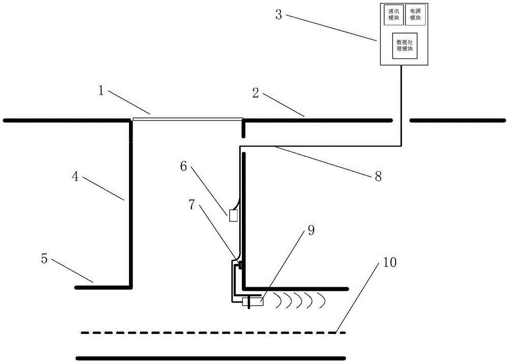
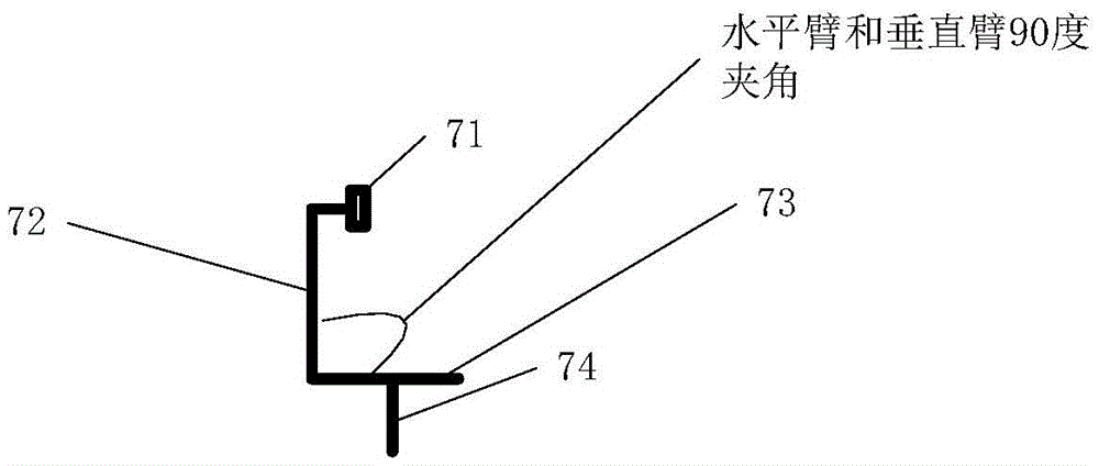
[0066] In this embodiment, the manhole drainage state monitoring system provided by the present invention includes a data collection box 3, a monitoring data collection unit, a float switch 6 and a mounting bracket 7; wherein, the data collection box 3 is electrically connected to the float ball The switch 6 and the monitoring data acquisition unit; the upper end of the mounting bracket 7 is used to connect the manhole wall 4, and the lower end extends to the drainage pipe 5; the monitoring ...


PUM


Abstract

The invention provides a draining state monitoring system and method of an inspection shaft. The system comprises a data collection box, a monitoring data collection unit, a float ball switch and an installation support, wherein the data collection box is electrically connected with the float ball switch and the monitoring data collection unit, the upper end of the installation support is connected to the wall of the inspection shaft, the lower end of the installation support extends to a drain pipe, the monitoring data collection unit is arranged at the lower end of the installation support, the float ball switch is arranged on the wall of the inspection shaft, the monitoring data collection unit is used to measure the draining flow velocity, the draining temperature and the liquid level pressure information of the drain pipe, and the float ball switch sends a switching signal to the data collection box when the liquid level in the inspection shaft rises to the installation position of the float ball switch. A Doppler ultrasonic flow velocity meter is connected to the wall of the inspection shaft via the installation support instead of being immersed in the flow for a long time, the physical survivability is greatly improved, the reliability of measurement data is improved, and physical damages are reduced.

Description

technical field [0001] The invention relates to the monitoring of the drainage state of municipal rainwater and sewage manholes, in particular to a system and method for monitoring the drainage state of manholes. Background technique [0002] The monitoring of the drainage status of municipal rainwater and sewage manholes is an important daily project of the urban underground drainage network, and it is also an important basic data source for the command and construction planning of urban waterlogging and flood discharge. Because the drainage pipe network is huge and complicated, and it is not easy to observe, it is necessary to use automatic sensing means to monitor the drainage status of manholes in real time without manual operation. The main indicators are the flow rate and flow of the manhole drainage pipeline and the manhole water level. [0003] Existing well-known solutions or technologies in the aforementioned field mainly monitor the drainage state of manholes thr...

Claims


Application Information

Patent Timeline
Patent Type & Authority Applications(China)
IPC IPC(8): G01P5/24G01F23/30
Inventor 魏忠慈施招扬
Owner SHANGHAI BOJOE SENSING TECH
Why Eureka
Try Eureka