
Cone beam CT cupping artifact correction method by utilizing energy function method

A technology of cupping artifacts and energy functions, applied in image data processing, instruments, calculations, etc., can solve problems such as low accuracy of scattering distribution estimation, no slice image correction, time-consuming Monte Carlo simulation method, etc.

Active Publication Date: 2016-04-27
NANJING UNIV OF POSTS & TELECOMM
View PDF9 Cites 5 Cited by
  • Summary
  • Abstract
  • Description
  • Claims
  • Application Information

AI Technical Summary

Problems solved by technology

[0007] (1) At present, the existing technology is mainly aimed at the correction of the projected image, and there is no correction directly aimed at the reconstructed slice image, such as the patent CN104408753A
[0008] (2) Most of the existing technologies focus on the method of artifact correction caused by scattering, and most of them need to add hardware equipment, such as: patents 200710019084 and 201310039298, both of which require expensive cone-beam CT equipment Adding hardware devices increases operational complexity and poses potential security risks to devices
Especially the patent 200710019084 needs to scan the measured object twice, which undoubtedly increases the radiation dose of the measured object
[0009] To sum up, among the methods in the prior art or literature, the Monte Carlo simulation method is very time-consuming, the correction result in the primary ray modulation method is limited by the structure of the modulation plate itself, and based on the partially scattered ray measurement method, it is necessary to increase Exposure dose, the estimation accuracy of the scattering distribution by existing methods is not high

Method used


Image

  • Cone beam CT cupping artifact correction method by utilizing energy function method
  • Cone beam CT cupping artifact correction method by utilizing energy function method
  • Cone beam CT cupping artifact correction method by utilizing energy function method

Examples


Embodiment Construction

[0042] The invention will be described in further detail below in conjunction with the accompanying drawings.

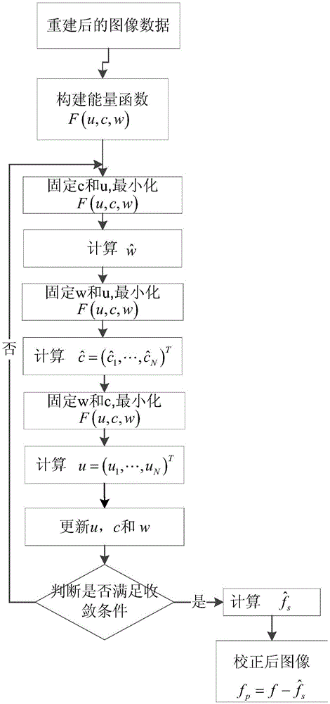
[0043] like figure 1 As shown, the present invention provides a method for correcting cup artifacts in cone beam CT using the energy function method, the method comprising the steps of:

[0044] Step 1: Obtain the reconstructed slice image according to the FDK algorithm, and it can be proved theoretically that the cupping artifact can be decomposed from the reconstructed image.

[0045] Step 2: Cupping Artifact Representation and Construction of Energy Function

[0046] F ( f s , f p ) = F ( u , c , w ) = ∫ Ω | f ( x ...


PUM


Abstract

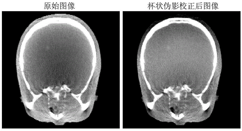
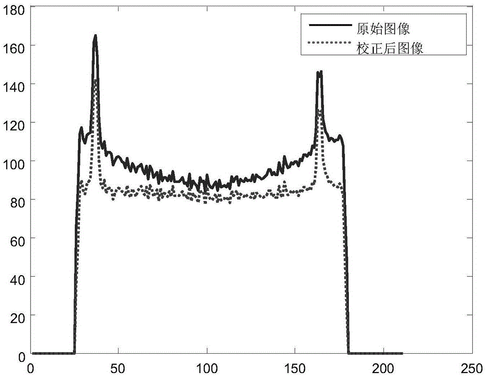
The invention discloses a cone beam CT cupping artifact correction method by utilizing an optimized energy function method. The method directly targets to users for re-established slice images and can finish correction work without making any change to original cone beam CT equipment, can carry out cone beam CT cupping artifact correction efficiently, and meanwhile, can improve CT value uniformity of the same substance of the reconstructed image, thereby helping improved volume visualization and development of visualization technology based on threshold value in the reconstructed image. The method is applied to the technical filed of correction of the cone beam CT reconstructed images (image domain).

Description

technical field [0001] The invention relates to the technical field of medical image processing, in particular to the technical field of cone-beam CT image cupping artifact correction and gray scale unevenness correction medical image processing technology. Background technique [0002] As a medical and industrial testing instrument developed in recent years, cone beam CT is often used in image-guided therapy, upper abdominal examination, oral examination, industrial testing, etc. Cone beam CT (CBCT) based on flat panel detectors has outstanding advantages compared with traditional two-dimensional CT, mainly in the fact that within one circular scan cycle of cone beam CT, hundreds or even thousands of tomographic images can be projected , has a higher scanning speed and radiation utilization, and effectively reduces the load output of the X-ray tube, reducing scanning costs. There are many factors affecting the image quality of cone-beam CT reconstruction, such as X-ray sca...

Claims


Application Information

Patent Timeline
IPC IPC(8): G06T5/00
CPCG06T2207/30008G06T2207/10081G06T5/80G06T5/70
Inventor 谢世朋马金辰庄文琴丁铭晨李海波
Owner NANJING UNIV OF POSTS & TELECOMM
Learn More