
Confocal microendoscopy system and adjusting method thereof

A technology of confocal microscopy and endoscopy, which is applied in the direction of endoscope, gastroscope, esophagus, etc., can solve the problems of complex coating process, damage, and occupation of the operator's energy, so as to achieve simple system operation, reduce manufacturing cost, and avoid manual operation. Adjustment effect

Active Publication Date: 2016-05-04
精微致远医疗科技(武汉)有限公司
View PDF8 Cites 15 Cited by
  • Summary
  • Abstract
  • Description
  • Claims
  • Application Information

AI Technical Summary

Problems solved by technology

Dust and humid environments usually cause varying degrees of damage to the optoelectronic devices of the above-mentioned probe-type confocal microendoscope system, resulting in system performance degradation or damage
[0006] (2) There is a large distance between the dichroic mirror, the long-pass filter and the spatial filter hole, so it cannot completely block and isolate the space stray light
[0007] (3) It is difficult and time-consuming to align the fluorescence focusing mirror with the spatial filter aperture (typical size is 20um)
[0008] (4) Due to the complex coating process, small dosage, and single supplier, the use of dichroic mirrors and long-pass filters in the system is relatively expensive
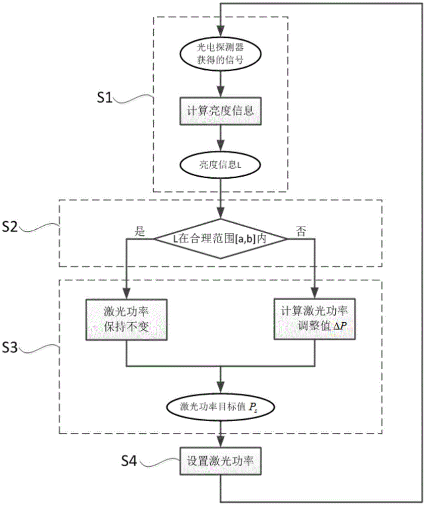
General probe-type confocal microendoscopes use manual adjustment of input laser power, and frequent manual adjustment of laser power will take up a lot of energy for the operator

Method used


Image

  • Confocal microendoscopy system and adjusting method thereof
  • Confocal microendoscopy system and adjusting method thereof
  • Confocal microendoscopy system and adjusting method thereof

Examples


Embodiment Construction

[0030] In order to make the object, technical solution and advantages of the present invention more clear, the present invention will be further described in detail below in conjunction with the accompanying drawings and embodiments. It should be understood that the specific embodiments described here are only used to explain the present invention, not to limit the present invention.

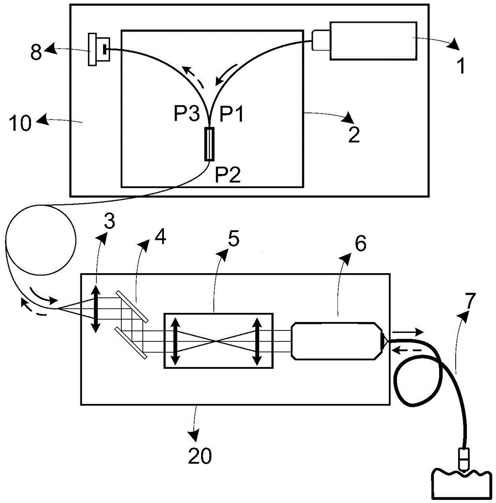
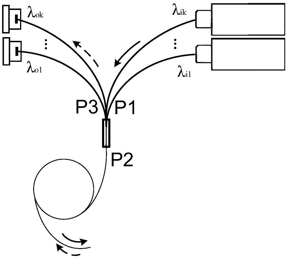
[0031] The invention provides a novel probe-type confocal microendoscope system with the function of automatic adjustment of input laser power, such as figure 1 As shown, the system includes a laser 1 for generating excitation light; a fiber optic circulator 2 for coupling excitation light and separating excitation light and fluorescence; a collimating lens group 3 for collimating excitation light and focusing fluorescence; deflection beam scanning device 4; relay lens group 5 for compressing deflection amplitude; coupling objective lens 6 for excitation light focusing and coupling; fiber optic ...


PUM


Abstract

The invention discloses a probe-based confocal microendoscopy system and an adjusting method thereof. The probe-based confocal microendoscopy system comprises a laser device, an optical fiber circulator, a collimating lens group, a light beam scanning device, a relay leans group, a coupling object lens, an optical fiber beam probe, a photoelectric detector and a control unit. The optical fiber circulator is provided with three ports, the first port P1 receives exciting light, and the second port P2 outputs coupled exciting light and receives fluorescent light; the third port P3 outputs the fluorescent light; the control unit is used for controlling the laser device, the light beam scanning device and the photoelectric detector, processing signals detected by the photoelectric detector so as to generate images, calculating and outputting laser power target values to the laser device according to the detected signals and controlling the laser device to generate existing light according to the laser power target value to achieve automatic adjustment of input laser power. By means of the probe-based confocal microendoscopy system and the adjusting method thereof, the signal to noise ratio of the system is raised, and manufacturing cost is lowered; frequent manual operation of an operator is avoided, and operation can be simpler and more convenient.

Description

technical field [0001] The invention belongs to the field of medical device manufacturing, and more specifically relates to a probe-type confocal microendoscope system with an automatic adjustment function of input laser power. Background technique [0002] Probe-based Confocal Laser Endomicroscopy (pCLE, probe-based Confocal Laser Endomicroscopy) is a kind of instrument that can extend into the human body with the help of gastroscope, colonoscope and other channels to obtain local histological images to realize microscopic lesions, gastrointestinal lesions and early gastrointestinal cancer. Medical equipment for accurate diagnosis. Because of its fast, accurate and non-invasive characteristics, it may replace traditional endoscopic biopsy and pathological examination in the near future, and become the main means and equipment for the diagnosis of gastrointestinal diseases and early gastrointestinal cancer. [0003] As described in documents such as CN99813284.5, CN02828322...

Claims


Application Information

Patent Timeline
Patent Type & Authority Applications(China)
IPC IPC(8): A61B1/00A61B1/273A61B1/31
CPCA61B1/00064A61B1/00165A61B1/00172A61B1/00186A61B1/2736A61B1/31
Inventor 万勇段西尧冯宇马骁萧
Owner 精微致远医疗科技(武汉)有限公司
Learn More