A construction method of underwater bottom-sealing concrete using steel truss reinforcement

An underwater back cover and construction method technology, which is applied in basic structure engineering, construction and other directions, can solve the problems of heavy weight, easy deformation of hoisting, high hoisting cost, achieve small plane area and weight, reduce construction risks, and hoist equipment capacity. small effect

Active Publication Date: 2017-06-16
CCCC SHEC FOURTH ENG +1
View PDF5 Cites 0 Cited by
  • Summary
  • Abstract
  • Description
  • Claims
  • Application Information

AI Technical Summary

Problems solved by technology

[0007] (2) Limitations of the traditional reinforced cage underwater bottom cover concrete:
[0008] 1) Overall hoisting is required: the steel cage needs to be hoisted as a whole, and it cannot be hoisted in pieces for underwater assembly into a whole
Since the reinforcement cage has a two-layer structure, and there are erection reinforcement and structural reinforcement in the middle, the reinforcement cage cannot be overlapped like a steel mesh; the number of vertical and horizontal main reinforcements of the reinforcement cage is large, and divers cannot use joints in the water like on land. butt joint length; also difficult to use welding joint length
[0009] 2) Hoisting is easy to deform, and the hoisting cost is high: when the steel cage is hoisted as a whole, due to the large area and heavy weight of the steel cage, large-scale lifting equipment is required for hoisting, the hoisting cost is high, and it is easy to cause deformation of the steel cage
[0010] 3) The top support affects the overall hoisting of the reinforcement cage: many foundation pits or cofferdams are equipped with multiple steel supports or reinforced concrete supports on the top, so the reinforcement cage cannot be hoisted in place as a whole
[0011] 4) It is difficult to place the conduits in place: since the bottom cover concrete needs to be poured with multiple conduits, and each conduit needs to be about 300mm away from the base surface when the first tank is poured, so the conduits must pass through the steel mesh on the top layer of the reinforcement cage. The distance between the main ribs of the sheet is much smaller than the diameter of the conduit, which prevents the conduit from being lowered into place
Of course, it can be considered to reserve conduit layout holes in advance when making the steel cage. However, due to the deep foundation pit, some of which reach 40 meters, it is still difficult to accurately install the conduits in place.
[0012] 5) It is difficult to remove the conduit: after pouring concrete, affected by the lateral pressure of the concrete, the conduit is often deflected to one side, close to the main reinforcement of the steel cage, causing the conduit to be stuck and difficult to lift
[0013] 6) Poor compactness and poor quality of back cover concrete: Since the conduit can only be installed above the bottom mesh of the reinforcement cage, when the first pot of concrete is poured, because the reinforcement cage is placed flat and the distance between the main bars of the mesh is small, when the first pot of concrete is poured, the bottom cover The concrete is directly impacted on the steel cage mesh, and the concrete cannot be vibrated with a vibrator, which may easily cause the concrete to be not compacted or even segregated
[0014] 7) It is easy to cause the reinforcement cage to float up, which affects the stress of the back cover concrete and the subsequent construction process: due to the small spacing between the main bars of the reinforcement cage mesh, it is easy to cause the reinforcement cage to float up, which not only affects the force of the back cover concrete
During the construction of the back-sealing concrete in the middle air shaft of the shield section, once the steel cage in the back-sealing concrete floats up to the shield section, the floating steel cage will also affect the smooth passage of the shield machine through the middle air shaft, which is very difficult to deal with

Method used


Image

  • A construction method of underwater bottom-sealing concrete using steel truss reinforcement
  • A construction method of underwater bottom-sealing concrete using steel truss reinforcement
  • A construction method of underwater bottom-sealing concrete using steel truss reinforcement

Examples


Embodiment Construction

[0041] The following non-limiting examples illustrate the invention.

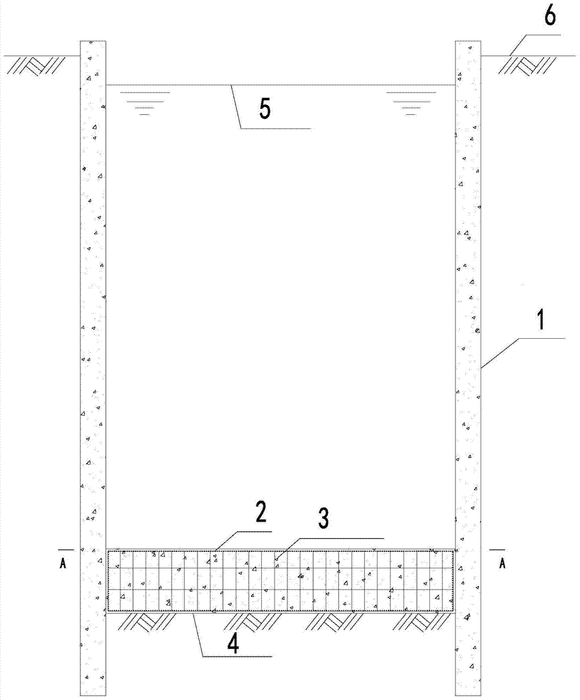
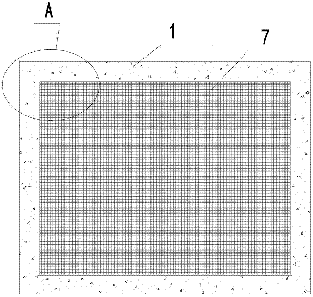
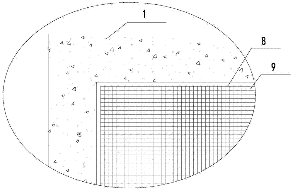
[0042] refer to Figure 4 , 5As shown, the underwater concrete structure reinforced with steel trusses is composed of steel trusses and underwater concrete 3. Steel trusses are used instead of steel cages for bending and tensile stress, so as to achieve the purpose of thinning the concrete on the back cover. Among them, the steel truss is composed of several horizontal rods 9, horizontal rods 10, vertical rods 11 and vertical and horizontal chords 12. Each rod of the truss can be processed by I-beam, H-beam or channel steel according to the force requirements. . The specific structure is: the steel truss is composed of an upper frame body, a lower frame body and an intermediate frame body connecting the upper and lower frame bodies. In a network structure, the middle frame is composed of vertical rods 11, horizontal chords 12 and longitudinal chords 12, and the vertical rods 11 are connected between the...


PUM


Abstract

The invention discloses an underwater bottom sealing concrete construction method using a steel truss for reinforcement and belongs to the field of underwater bottom sealing for deep foundation pit construction. The underwater bottom sealing concrete construction method using the steel truss for reinforcement comprises the steps that after a cofferdam is installed or an underground diaphragm wall is constructed, underwater excavation is conducted in a foundation pit till the bottom elevation of bottom sealing concrete is reached; the steel truss is machined piece by piece or integrally on site on land; the steel truss is hoisted and lowered in place integrally or piece by piece; a bottom sealing platform is built, a central collection hopper and a chute are arranged, and a plurality of bottom sealing guide pipes are lowered; mixed concrete is conveyed to the site; tank opening is conducted step by step for head sealing construction, and then normal pouring is conducted; and the bottom sealing guide pipes, the central collection hopper, the chute and the bottom sealing platform are dismounted after bottom sealing is completed, and water pumping is conducted after the strength of the bottom sealing concrete reaches the design strength. By the adoption of the underwater bottom sealing concrete construction method using the steel truss for reinforcement, the reinforcement effect can be achieved, and the thickness of the bottom sealing concrete is reduced, so that the purpose of reducing the construction cost is achieved, the construction difficulty of the underwater bottom sealing concrete can be lowered, and the construction quality and construction safety of the bottom sealing concrete are guaranteed.

Description

technical field [0001] The invention belongs to a novel underwater bottom sealing concrete designed to ensure dry working conditions in deep foundation pits in the construction of deep foundation pits in the field of bridge construction and in the construction of interval air shafts in the field of urban rail transit construction. It is suitable for underwater sealing of all kinds of deep foundation pit construction. Background technique [0002] In the construction of the bridge foundation, due to the deep embedding of the cap and the deep excavation of the foundation pit, in order to ensure that the cap can form a dry construction, it is necessary to pour underwater concrete in the cofferdam to seal the bottom. Sometimes due to the deep excavation depth, there is a large water pressure head inside and outside the cofferdam, which causes the back cover concrete to bear a large water pressure. The depth of the lowering of the cofferdam, the total height and the total weight...

Claims


Application Information

Patent Timeline
Patent Type & Authority Patents(China)
IPC IPC(8): E02D19/18E02D15/06
CPCE02D15/06E02D19/18E02D2250/0023E02D2250/0061
Inventor 廖正根尤田何承海李桂华
Owner CCCC SHEC FOURTH ENG
Why Eureka
Try Eureka