Novel two-way insert type oscillation control valve

A vibration control and cartridge valve technology, applied in valve details, valve devices, engine components, etc., can solve the problems of polluting the environment, leakage of hydraulic components and pipelines, affecting the work quality of rollers, and operator comfort, etc. The effect of low cost, increased oil passage area, and shortened vibration stop time

Inactive Publication Date: 2016-05-04
PERMCOTIANJINHYDRAULIC INC
View PDF5 Cites 4 Cited by
  • Summary
  • Abstract
  • Description
  • Claims
  • Application Information

AI Technical Summary

Problems solved by technology

When the vibratory roller starts to vibrate, its vibrating hydraulic motor starts with load, resulting in a high-pressure shock to the hydraulic system during the start-up stage of the roller. This instantaneous high pressure will give components such as pumps, valves, motors and pipelines in the hydraulic system Bring bad noise, cause damage to hydraulic components and loose pipeline connections, resulting in leakage and environmental pollution. According to statistical analysis, more than 60% of the failures in the vibration hydraulic system of the road roller are caused by the high pressure of the vibration; when the vibration is stopped, due to The rotational inertia of the exciter rotor of the roller will cause the vibration stop time to be too long and cause the whole machine to resonate, which will affect the working quality of the roller and the working comfort of the operator

Method used


Image

  • Novel two-way insert type oscillation control valve
  • Novel two-way insert type oscillation control valve
  • Novel two-way insert type oscillation control valve

Examples


Embodiment Construction

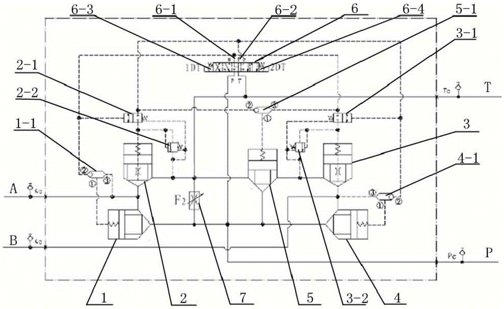
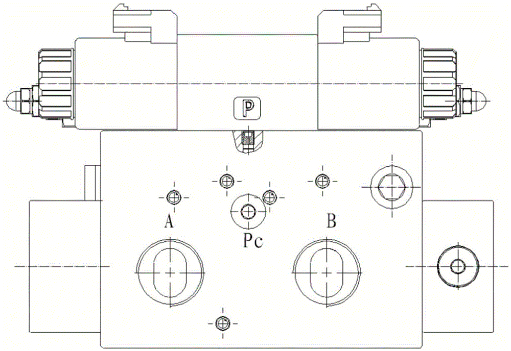
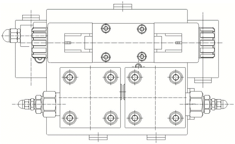
[0038] Such as Figure 1 to Figure 3As shown, a novel two-way plug-in vibration control valve of the present invention includes a valve body, a plug-in cavity is formed on the valve body, and an oil inlet port P communicated with the oil outlet of the hydraulic pump, and connected with the hydraulic system The oil return interface T connected to the oil tank of the hydraulic motor, the first working interface A and the second working interface B respectively communicated with the first oil port and the second oil port at both ends of the hydraulic motor; the main circuit, the main circuit is inserted in the In the cartridge cavity of the valve body, there are five two-way cartridge valves and a pilot direction control circuit composed of a three-position four-way electromagnetic reversing valve 6, wherein the first two-way cartridge valve 1 is set at the oil inlet Between the port P and the first working port A, the liquid supply from the oil inlet port to the first working po...


PUM


Abstract

The invention belongs to the field of two-way insert type oscillation control valves, and particularly relates to a novel two-way insert type oscillation control valve which comprises a valve body, a main loop, an oscillation stop branch loop and a no-load oil return branch loop. The valve body is provided with an insert cavity, an oil inlet connector, an oil return connector, a first working interface and a second working interface. The main loop is inserted in the insert cavity of the valve body, and comprises a pilot direction control loop composed of five two-way insert valves and a three-position four-way electromagnetic reversing valve. The oscillation stop branch loop comprises a control large oscillation stop and a control small oscillation stop. When an engine idles or a road roller does not oscillate, the no-load oil return of a hydraulic pump is achieved through the no-load oil return branch loop. An adjustable throttling valve is arranged between the oil inlet interface and the oil return interface and on the valve and is used for adjusting the flow entering a motor. The valve has the advantages that hydraulic impact during oscillation of the road roller is reduced, oscillation stop time is shortened, resonance of the whole machine is avoided, two oscillation amplitudes can be switched, and oscillation frequency can be adjusted within a certain range.

Description

technical field [0001] The invention belongs to the technical field of a two-way plug-in type vibration control valve, in particular to a novel two-way plug-in type vibration control valve for controlling the operation of a hydraulic motor on a vibratory road roller. Background technique [0002] At present, the vibrating device of domestic single-drum vibratory roller adopts the open hydraulic transmission and control system with constant pump (mostly gear pump) as the power source, which is relatively common. When the vibratory roller starts to vibrate, its vibrating hydraulic motor starts with load, resulting in a high-pressure shock to the hydraulic system during the start-up stage of the roller. This instantaneous high pressure will give components such as pumps, valves, motors and pipelines in the hydraulic system Bring bad noise, cause damage to hydraulic components and loose pipeline connections, resulting in leakage and environmental pollution. According to statisti...

Claims


Application Information

Patent Timeline
Patent Type & Authority Applications(China)
IPC IPC(8): F15B13/04F16K31/06
CPCF15B13/04F16K31/06
Inventor 吴东升郭熛张志云孙波
Owner PERMCOTIANJINHYDRAULIC INC
Why Eureka
Try Eureka