
Pulverized coal distributer capable of adjusting air speed and pulverized coal concentration

An adjustable and distributor technology, applied in the direction of block/powder supply/distribution, supply configuration, combustion method, etc., can solve problems such as insufficient combustion, air powder mismatch, over-temperature and high-temperature corrosion

Active Publication Date: 2016-05-04
SHANGHAI POWER EQUIP RES INST
View PDF5 Cites 5 Cited by
  • Summary
  • Abstract
  • Description
  • Claims
  • Application Information

AI Technical Summary

Problems solved by technology

[0005] Due to the deviation of the amount of pulverized coal, it will lead to a large deviation of the local heat load of the boiler, which will cause the heat deviation of the outlet of the boiler furnace
[0006] (2) Local overheating and high temperature corrosion
[0007] Due to the deviation of the amount of pulverized coal, it will lead to the imbalance of air-coal ratio in some areas, and the area with large amount of coal will easily lead to overheating of local water-cooled wall pipes due to high heat load
In addition, the area with high powder content is likely to cause insufficient oxygen, and the reducing atmosphere is severe, which will cause high temperature corrosion for a long time
[0008] (3) Insufficient combustion
[0009] Due to the deviation of the amount of pulverized coal, it will cause local wind and powder mismatch: the area with a large amount of powder may not necessarily have a large air volume, which will cause local hypoxia and greatly restrict the burnout of pulverized coal.
[0010] (4) Fluctuation of steam temperature and pressure with variable load
[0011] Due to the deviation of the amount of pulverized coal, the air powder will be mixed unevenly, which will easily cause the local ignition time in the furnace to vary, and the combustion structure will deteriorate, which will cause fluctuations in steam temperature, steam pressure and furnace negative pressure.
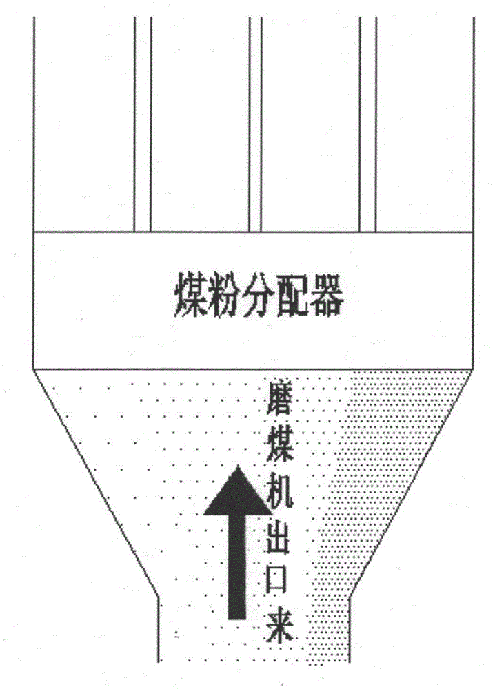
[0012] As mentioned above, the pulverized coal distributor has a great influence on the combustion of the boiler, but at present, many power plants have not installed the pulverized coal distributor, because the pulverized coal distributor currently on the market is a grid type or a line ,like figure 1 As shown, the primary air ducts at the outlet of the pulverized coal distributor are arranged from left to right, and the pulverized coal concentration at the outlet of the pulverizer is due to the relationship between the airflow rotation and local resistance in the pulverizer, and the pulverized coal concentration at the left and right sides usually appears. In the case of large deviation, that is, the concentration of pulverized coal on the left (right) side is several times that of the pulverized coal on the right (left) side. It is difficult to achieve the balance of powder volume and wind speed in each primary air duct through adjustment
In summary, because the design of the traditional pulverized coal distributor does not take into account the large deviation of the pulverized coal concentration on the left and right sides, the traditional pulverized coal distributor has poor adjustability in actual use

Method used


Image

  • Pulverized coal distributer capable of adjusting air speed and pulverized coal concentration
  • Pulverized coal distributer capable of adjusting air speed and pulverized coal concentration
  • Pulverized coal distributer capable of adjusting air speed and pulverized coal concentration

Examples


Embodiment Construction

[0029] The present invention will be further described below in conjunction with specific embodiments. It should be understood that these examples are only used to illustrate the present invention and not to limit the scope of the present invention. In addition, it should be understood that after reading the content taught by the present invention, those skilled in the art can make various changes or modifications to the present invention, and these equivalent forms also fall within the scope defined by the appended claims of the present application.

[0030] In order to make it easier to understand the use of this pulverized coal distributor, now take a 300MW four-corner tangential boiler as an example to illustrate. The pulverized coal distributor is installed on the outlet pipe of the coal mill of the power station boiler, and the outlet of the coal mill is equipped with 4 primary air Tube.

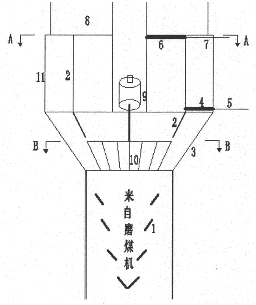
[0031] figure 2 The structural schematic diagram of the pulverized coal distrib...


PUM


Abstract

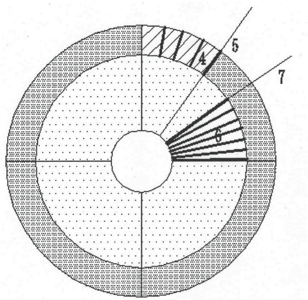
The invention provides a pulverized coal distributer capable of adjusting the air speed and the pulverized coal concentration. The pulverized coal distributer comprises a light-phase inner pipe coaxially arranged inside a pulverized coal drum of a coal mill outlet . A dense-phase outer circular ring is formed between the light-phase inner pipe and the drum wall of the pulverized coal drum of the coal mill outlet. The section of the light-phase inner pipe and the section of the dense-phase outer circular ring are coaxially and evenly divided into parts of the same number as primary air pipes. Each equational section is connected with one primary air pipe and provided with a light-phase regulating valve and a dense-phase regulating valve. Rotating blades are arranged in a reducer pipe at the front end of the pulverized coal drum of the coal mill outlet. A shutter ring is arranged at the front end of the reducer pipe. Pulverized coal at the coal mill outlet is compressed twice through the shutter ring and the rotating blades; after two times of light-dense separation under the inertia effect, dense pulverized coal is concentrated at the outer circular ring, light pulverized coal is distributed at the inner circular ring, the dense pulverized coal and the light pulverized coal are evenly divided, each part of the dense pulverized coal and each part of the light pulverized coal are mixed and enter the corresponding primary air pipe, and all pulverized coal is distributed evenly; each part of light-dense pulverized coal is provided with one regulating valve so as to be regulated conveniently.

Description

technical field [0001] The invention relates to a pulverized coal distributor in a thermal power plant, in particular to a pulverized coal distributor capable of evenly distributing air volume and pulverized coal concentration to each primary air duct of the same coal mill. Background technique [0002] The pulverized coal distributor is generally used on the main pulverized coal pipeline at the outlet of the coal mill. Through the distribution of the pulverized coal distributor, it can achieve the purpose of evenly distributing the air volume and the amount of pulverized coal for each primary air duct of the same coal mill. [0003] Whether the pulverized coal distribution of each primary air duct at the outlet of the coal mill is evenly distributed has a great influence on the combustion of the boiler. When the coal distribution is uneven, the actual amount of pulverized coal entering each burner varies greatly, and the air-powder ratio is prone to mismatch, resulting in t...

Claims


Application Information

Patent Timeline
Patent Type & Authority Applications(China)
IPC IPC(8): F23K3/02
CPCF23K3/02F23K2203/201
Inventor 周文台何翔曹建文杨勇魏增涛孟永杰
Owner SHANGHAI POWER EQUIP RES INST
Learn More