Three-dimensional micro-nano trigger probe

A trigger probe and micro-nano technology, applied in the field of micro-nano testing, can solve the problems of low detection sensitivity and precision of strain gauges, difficult installation and adjustment, complex structure, etc., and achieve the effect of clear measurement, simple and applicable method, and high sensitivity

Active Publication Date: 2018-04-06
ANHUI ELECTRICAL ENG PROFESSIONAL PROFESSIONAL TECHN COLLEGE +3
View PDF8 Cites 0 Cited by
  • Summary
  • Abstract
  • Description
  • Claims
  • Application Information

AI Technical Summary

Problems solved by technology

The existing probe needs to integrate two to four high-precision sensors, which has the problems of complex structure, difficult installation and adjustment, and high cost
For example, the strain gauge-based three-dimensional micro-contact sensing probe developed by the University of Eindhoven in the Netherlands is to make the strain gauge, circuit and elastic elements into an overall structure through precipitation, plate making, etching and other processes. The change of displacement and displacement is detected by the strain gauge installed on the sensitive beam, which is small in size, but the detection sensitivity and accuracy of the strain gauge are relatively low, and the measuring head adopts a triangular topology, which makes the decoupling complicated
The electromagnetic micro-contact probe developed by METAS, the Swiss Federal Bureau of Metrology and Inspection, has three degrees of freedom. The detection in each direction is realized by inductance. The force measurement in the three directions is the same. The structure is mainly made of aluminum. , the electromagnetic probe has a large measurement range, high lateral detection sensitivity and small contact force, but its structure is quite complicated, difficult to install and adjust, and it adopts a triangular suspension structure, which makes decoupling complicated

Method used


Image

  • Three-dimensional micro-nano trigger probe
  • Three-dimensional micro-nano trigger probe
  • Three-dimensional micro-nano trigger probe

Examples


Embodiment Construction

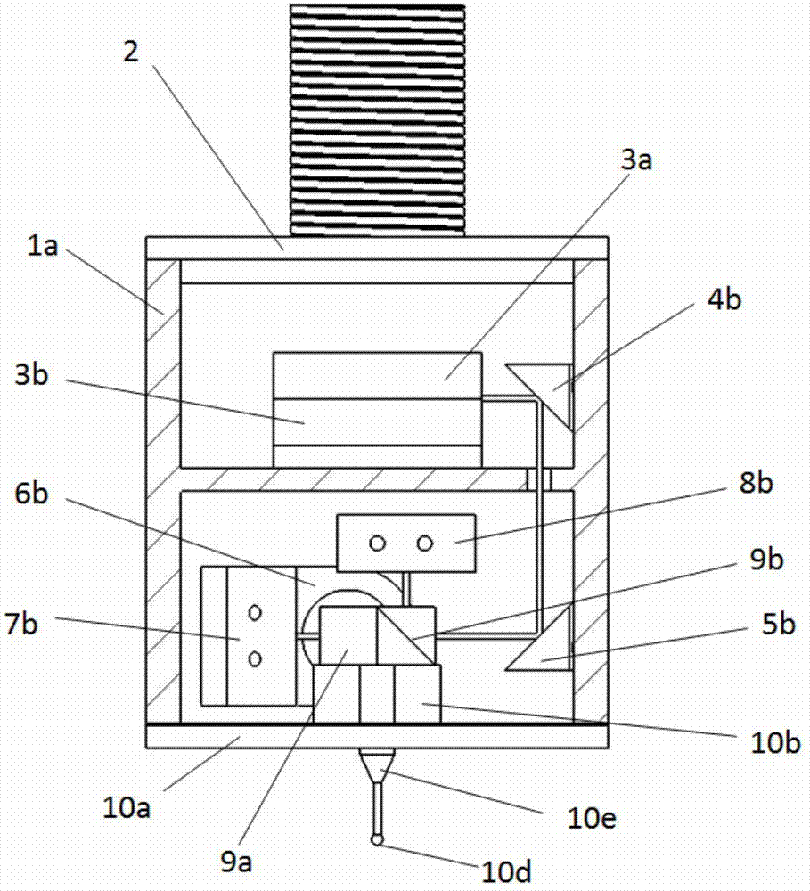
[0043] In this embodiment, the three-dimensional micro-nano trigger probe is composed of a probe unit and a measurement unit.

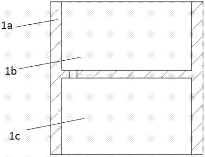
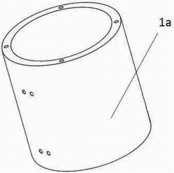
[0044] See figure 2 , image 3 , Figure 5 , Image 6 with Figure 7 , The probe unit is provided with a reed 10c in the shape of a "cross" on the ring seat 10a, Figure 8 The distal end of each cantilever of the reed 10c shown is formed integrally with the outer ring of the circular reed, and is fixedly connected to the circular base 10a by the outer ring of the circular reed; on the upper surface of the reed 10c, The center of the reed 10c is fixedly provided with a suspension sheet 10b in the shape of a "cross" to form a suspension structure of the suspension sheet 10b on the ring seat 10a; the upper end surface of the suspension sheet 10b is respectively fixedly provided with a first dichroic reflecting prism 9a and a second The spectroscopic reflection prism 9b and the wedge prism 9c are fixedly installed with a probe 10e in the central through hole...


PUM


Abstract

The invention discloses a three-dimensional micro-nano trigger probe, which is characterized in that it is composed of a measuring head unit and a measuring unit: the measuring head unit is provided with a reed in the shape of a "ten" on a circular seat, and is fixed on the reed in the shape of The "ten" suspension piece forms a suspension structure of the suspension piece on the ring seat; each light splitting reflective prism and wedge-shaped prism are respectively fixed on the upper end surface of the suspension piece, and the probe is fixedly installed in the central through hole of the suspension piece; The measurement unit is composed of a laser and a four-quadrant detector, and the displacement signal of the measuring ball at the front end of the probe is obtained by using the four-quadrant detector. The invention can obtain the detection effect of high precision, high sensitivity and small force, and has the advantages of high stability and flexible adjustment.

Description

Technical field [0001] The invention relates to the field of micro-nano testing, and more specifically to a trigger type three-dimensional probe applied to a nano three-coordinate measuring machine for three-dimensional high-precision measurement of the surface of an object. Background technique [0002] In recent decades, nanotechnology has advanced by leaps and bounds, and the manufacturing industry has entered the nanofabrication stage. Miniaturization and precision are the core driving force for development. The improvement of manufacturing technology inevitably requires the cooperation of precision measurement technology, so that the high precision of the manufacturing industry can be guaranteed. Therefore, precision measuring equipment plays an important role in precision manufacturing and is an essential part of precision manufacturing. However, precision manufacturing is inseparable from precision processing. With the rapid development of precision processing technology...

Claims


Application Information

Patent Timeline
Patent Type & Authority Patents(China)
IPC IPC(8): G01B11/00
CPCG01B11/007G01B5/012
Inventor 李瑞君程琳周斌程真英陈晶
Owner ANHUI ELECTRICAL ENG PROFESSIONAL PROFESSIONAL TECHN COLLEGE
Why Eureka
Try Eureka