Lubricating oil nozzle flow two-CCD-camera measure system and method

A technology of binocular vision measurement and lubricating oil nozzles, which is applied in fixed measurement chambers, signal transmission systems, instruments, etc., can solve the problem of complex image processing algorithms in imaging systems, inability to directly output flow detection results, and unsuitability for multi-nozzle flow measurement Test and other issues to achieve the effect of reducing background signal interference, ensuring safety and health, and reducing difficulty

Inactive Publication Date: 2016-05-04
CHINA AVIATION POWER MACHINE INST
View PDF6 Cites 0 Cited by
  • Summary
  • Abstract
  • Description
  • Claims
  • Application Information

AI Technical Summary

Problems solved by technology

In the environment of lubricating oil atomization, testers need to wear masks and protective clothing for on-site operations, which is very inconvenient
Moreover, this direct contact measurement method of the human body has certain potential safety hazards, threatening the health of the test personnel.
[0004] In the prior art, there is a non-contact liquid level measurement device based on machine vision, but the imaging system and image processing algorithm of the device are complex, and the flow detection results cannot be directly output
[0005] Although there is also a monocular vision liquid level measurement system with a relatively simple structure, it only proposes the reading measurement of the glass gauge, and cannot directly perform flow detection; and its imaging system needs to calibrate the optical axis of the camera and the cylinder vertically when it is used. The operation is difficult; if there is an error in the calibration, it will have a great impact on the measurement accuracy, resulting in a low stability of its accuracy; and the monocular vision measurement can only measure one measuring cylinder in one field of view, which is not suitable for multiple nozzles at the same time Carry out flow measurement test, the efficiency is relatively low

Method used


Image

  • Lubricating oil nozzle flow two-CCD-camera measure system and method
  • Lubricating oil nozzle flow two-CCD-camera measure system and method
  • Lubricating oil nozzle flow two-CCD-camera measure system and method

Examples


Embodiment 1

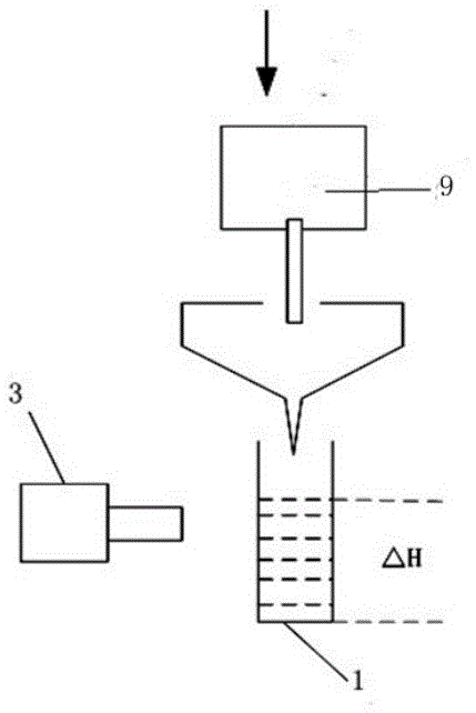
[0041] Such as figure 1 As shown, this embodiment provides a binocular visual measurement system for oil nozzle flow, including an imaging subsystem, an acquisition subsystem, and a processing subsystem connected in sequence; the imaging subsystem includes two light sources 2 that provide light sources for the imaging subsystem , two cameras 3; the acquisition subsystem includes a wireless image transmitter 4 for receiving camera 3 image signals, a wireless image receiver 5 for receiving signals of the wireless image transmitter 4 and a wireless image receiver 5 for sending The image acquisition card 6 for collecting image signals; the wireless image transmitter 4 is connected with the wireless image receiver 5 through wireless communication; the wireless image receiver 5 is connected with the image acquisition card 6; the processing subsystem includes processing the signal sent by the image acquisition card 6 The processing server 7; the server 7 includes image processing and...


PUM


Abstract

The invention discloses a lubricating oil nozzle flow two-CCD-camera measure system and method. The system comprises an imaging subsystem, an acquisition subsystem and a processing subsystem which are connected in sequence, wherein the imaging subsystem comprises two light sources and two cameras, the acquisition subsystem comprises a wireless image transmitter, a wireless image receiver and an image capture card, the wireless image transmitter is in wireless communication with the wireless image receiver, and the wireless image receiver and the image capture card are connected; the processing subsystem comprises a server used for processing image signals, and the server comprises image processing and automatic flow calculation software. The system can be used simply by making a substance to be measured within the field range of the cameras, and measurement is easier; furthermore, measurement of the flow of multiple nozzles can be conducted at the same time, and measurement efficiency is high; the system has the advantages of being simple in structure, high in measurement precision and high in stability.

Description

technical field [0001] The invention relates to a binocular vision measurement system and method for lubricating oil nozzle flow. Background technique [0002] The flow rate of the lubricating oil nozzle of the aeroengine is an important parameter of the engine, which is related to the lubrication condition of the main friction pairs on the engine, and affects the working state and working life of the aeroengine. Therefore, a lubricating oil nozzle test is required to measure the flow rate of the lubricating oil nozzle. However, high-temperature lubricating oil is required to simulate actual working conditions in the lubricating oil nozzle test, and the high-temperature lubricating oil in the measurement environment will emit toxic and odorous gases. [0003] At present, the flow measurement of lubricating oil nozzles mainly adopts the measurement method of measuring cylinder and relying on manual reading. In the environment of lubricating oil atomization, testers need to ...

Claims


Application Information

Patent Timeline
Patent Type & Authority Applications(China)
IPC IPC(8): G01F11/28G08C17/02
CPCG01F11/28G08C17/02
Inventor 李光乐曹鹏郭晖谭锋郑鹏常艳祥
Owner CHINA AVIATION POWER MACHINE INST
Why Eureka
Try Eureka