Evanescent-wave type photoacoustic spectrum trace gas sensor based on optical fiber resonant cavity and measurement method

A technology of optical fiber resonator and photoacoustic spectroscopy, which is applied in the field of laser sensors to achieve the effect of improving detection sensitivity and increasing laser excitation power

Active Publication Date: 2016-05-04
HARBIN INST OF TECH
View PDF8 Cites 8 Cited by
  • Summary
  • Abstract
  • Description
  • Claims
  • Application Information

AI Technical Summary

Problems solved by technology

Quartz-enhanced photoacoustic spectroscopy sensor is a common gas sensor. In this sensor, the detection sensitivity of the sensor is proportional to the laser power at the quartz tuning fork...

Method used


Image

  • Evanescent-wave type photoacoustic spectrum trace gas sensor based on optical fiber resonant cavity and measurement method

Examples


specific Embodiment approach 1

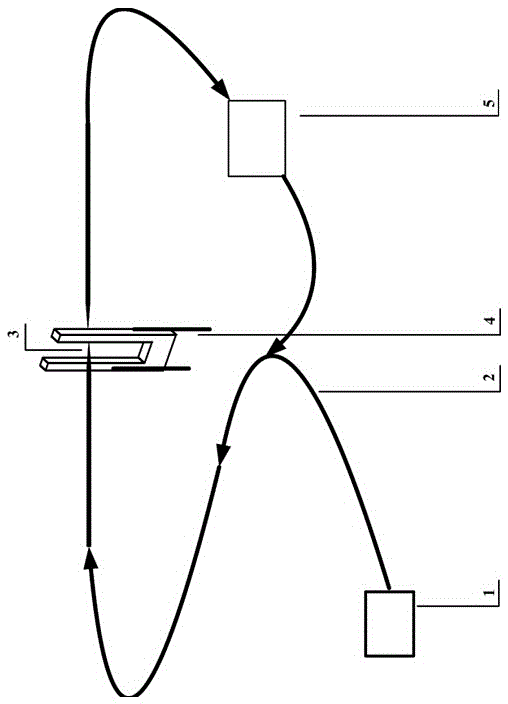
[0013] Specific implementation mode one: as figure 1 As shown, the optical fiber cavity-based evanescent photoacoustic spectrum trace gas sensor provided in this embodiment is composed of a semiconductor laser source 1, an optical fiber combiner 2, a tapered optical fiber 3, a quartz tuning fork 4, and a phase modulator 5. The tapered optical fiber 3 passes through the prongs of the quartz tuning fork 4, and the laser light emitted by the semiconductor laser source 1 is transmitted to the tapered optical fiber 3 through the fiber beam combiner 2, and the evanescence of strong energy is generated at the tapered optical fiber 3. At the same time, the phase modulator 5 enables the optical fiber combiner 2 to form an optical resonant cavity to further enhance the energy of the evanescent wave field. The gas to be measured absorbs the energy of the evanescent wave field to generate sound waves, and the quartz tuning fork 4 receives the sound wave signal. Inversion of gas concentrat...

specific Embodiment approach 2

[0022] Specific Embodiment 2: This embodiment provides a method for realizing trace gas concentration measurement using an evanescent photoacoustic spectrum trace gas sensor based on a fiber resonator, which is realized by the following steps:

[0023] Step 1. The laser light emitted by the semiconductor laser source 1 is input into the fiber combiner 2. After passing through the phase modulator 5, the fiber combiner forms an optical resonant cavity. The laser power in the fiber is amplified and enhanced, and then the tapered fiber is made 3 places Generate a strong optical evanescent field;

[0024] Step 2: The target gas to be measured absorbs the energy of the evanescent wave field at the tapered optical fiber to generate an acoustic wave field, and the quartz tuning fork 4 detects the acoustic wave signal to invert the gas concentration.

[0025] In this embodiment, the concentration of the target gas to be measured cannot be lower than the ppb level.

[0026] In this emb...


PUM

PropertyMeasurementUnit
Transmission lossaaaaaaaaaa
Resonance frequencyaaaaaaaaaa

Abstract

The invention discloses an evanescent-wave type photoacoustic spectrum trace gas sensor based on an optical fiber resonant cavity and a measurement method. The sensor is composed of a semiconductor laser source, an optical fiber combiner, a tapered optical fiber, a quartz tuning fork and a phase modulator. The measurement method comprises the following steps that (1) laser emitted by the semiconductor laser source is input into the optical fiber combiner, and the laser passes through the phase modulator, so that the optical fiber combiner is formed into an optical resonant cavity, and the laser power in optical fiber is amplified and enhanced, therefore a stronger optical evanescent field is generated in the position of the tapered optical fiber; (2) to-be-measured target gas absorbs the energy of an evanescent wave field in the position of the tapered optical fiber, so that an acoustic wave field is generated; the quartz tuning fork is used for detecting an acoustic wave signal and inverting gas concentration. The evanescent-wave type photoacoustic spectrum trace gas sensor based on the optical fiber resonant cavity and the measurement method have the advantages that the laser excitation power is effectively improved, therefore the detection sensitivity of a photoacoustic spectrum gas sensor is greatly improved.

Description

technical field [0001] The invention belongs to the field of laser sensors, and relates to an evanescent wave type photoacoustic spectrum trace gas sensor and a gas measurement method based on an optical fiber resonant cavity. Background technique [0002] Trace gas sensor technology can detect the composition and concentration of gas, and has important applications in the fields of environmental monitoring, atmospheric physics and dangerous gas monitoring. Quartz-enhanced photoacoustic spectroscopy sensor is a common gas sensor. In this sensor, the detection sensitivity of the sensor is proportional to the laser power at the quartz tuning fork. Therefore, in order to improve the detection sensitivity of the sensor, it is generally necessary to use High lasers, but so far, the output power of common semiconductor lasers is less than 50mW. [0003] If the laser beam is cyclically transmitted in the ring-shaped closed optical fiber, the phase modulator can be used to make thi...

Claims


Application Information

Patent Timeline
IPC IPC(8): G01N21/17
CPCG01N21/1702G01N2021/1704
Inventor 马欲飞于欣陈默然李旭东彭江波何应闫仁鹏樊荣伟董志伟李晓晖陈德应
Owner HARBIN INST OF TECH
Why Eureka
Try Eureka