Brushless motor and motor control device

A technology for motor control and brushless motors, applied in motor generator control, motor control, electronic commutation motor control, etc., can solve problems such as high temperature and inability to ensure torque

Active Publication Date: 2016-05-04
DENSO CORP
View PDF9 Cites 9 Cited by
  • Summary
  • Abstract
  • Description
  • Claims
  • Application Information

AI Technical Summary

Problems solved by technology

[0006] However, because the winding set of the motor is heated by passing electricity, the heat is radiated, so there is a possibility that the permanent magnets of the motor become hot
In particular, there is a possibility that the motor used for EPS becomes hot due to outputting assist torque for continuous steering operations (for example, parking in a garage)
Therefore, in order to prevent demagnetization of the neodymium magnet, the extent to which the limit value of the maximum energized current is reduced or the frequency becomes high, which leads to a risk that sufficient torque cannot be ensured

Method used


Image

  • Brushless motor and motor control device
  • Brushless motor and motor control device
  • Brushless motor and motor control device

Examples


no. 1 example

[0036] (steering system)

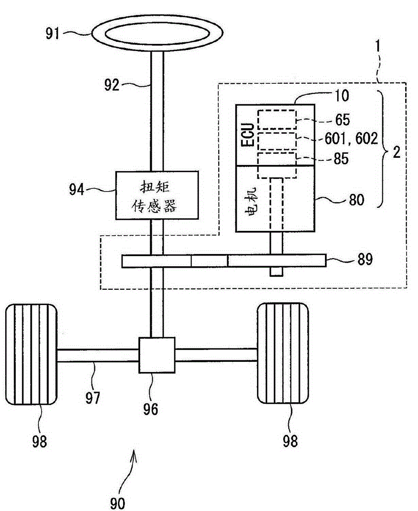
[0037] figure 2 The overall configuration of a steering system 90 having the electric power steering apparatus 1 is illustrated. A torque sensor 94 for detecting steering torque is mounted on a steering shaft 92 connected to the steering device 91 . A pinion 96 is provided at the front end of the steering shaft 92 , and the pinion 96 meshes with the rack shaft 97 . A pair of wheels 98 are rotatably coupled to both ends of the rack shaft 97 via tie rods. The rotational motion of the steering shaft 92 is converted into a linear motion of the rack shaft 97 through the pinion 96 , and the pair of wheels 98 is steered at an angle corresponding to the linear motion displacement of the rack shaft 97 .

[0038] The electric power steering apparatus 1 includes a drive device 2 that rotates a rotation shaft and a reduction gear 89 that decelerates the rotation of the rotation shaft and transmits the decelerated rotation to a steering shaft 92 .

[0039] T...

no. 2 example

[0132] will refer to Figure 16 with Figure 17 A second embodiment of the present disclosure will be described. In the second embodiment, components substantially the same as those in the first embodiment are denoted by like reference numerals, and duplicate descriptions thereof will be omitted.

[0133] The control unit 66 according to the second embodiment includes: current command value calculation units 151, 152, maximum current limiting units 161, 162, three-phase / two-phase conversion units 391, 392, controllers 301, 302, two-phase / three-phase Phase conversion units 381 , 382 , fault detection units 711 , 712 , temperature estimation unit 74 and temperature rise control unit 76 .

[0134] The control unit 66 includes a configuration corresponding to each of the first system and the second system as in the first embodiment. In symbols of components and physical quantities corresponding to the respective systems, "1" is appended to the end of symbols in the first system...


PUM


Abstract

A brushless motor (80) for an electric power steering device (1) that assists a steering operation includes: a stator (30) having a plurality of winding sets (801,802) for a plurality of systems respectively; and a rotator (40) having a ferrite magnet (43). In the motor, a maximum current flowing without any demagnetization at high temperature is large. Hence, the torque of the motor is easily ensured at high temperature. In particular, when a failure occurs in one system, it is easy to ensure the torque of the normal system even at high temperature.

Description

technical field [0001] The present disclosure relates to a brushless motor and a motor control device in an electric power steering device. Background technique [0002] Hitherto, an electric power steering device (EPS, electric power steering device) in which steering operation is assisted by a driving force of a motor has been used in a vehicle steering system. In EPS, it is known (for example, PTL1) that a brushless motor comprises multiple systems, each of which has an inverter and a winding set controlled by the inverter from a fail-safe point of view power on. In this type of motor, when either system fails, the power converter and winding set in the normal system continue to drive. [0003] By the way, the motor of EPS is mainly a permanent magnet rotation type, and it is necessary to obtain a strong magnetic flux density by setting a small permanent magnet of the rotor. Therefore, in the prior art such as PTL1, a neodymium magnet having a high magnetic flux densit...

Claims


Application Information

Patent Timeline
Patent Type & Authority Applications(China)
IPC IPC(8): H02K29/00H02P21/00H02P21/16B62D5/04
CPCH02P29/66B62D5/0403B62D5/046B62D5/0496H02P25/22H02K3/28
Inventor 加纳辽铃木崇志株根秀树
Owner DENSO CORP
Why Eureka
Try Eureka