Generator for motorcycle

A technology for motorcycles and generators, applied to synchronous motors with stationary armatures and rotating magnets, magnetic circuit shape/pattern/structure, magnetic circuit stationary parts, etc. Power generation output and power generation efficiency are reduced, and the power loss of the generator is reduced, so as to achieve the effect of increasing power generation output, improving power generation efficiency, and reducing power loss.

Inactive Publication Date: 2016-05-04
SUZUKI MOTOR CO LTD
View PDF9 Cites 2 Cited by
  • Summary
  • Abstract
  • Description
  • Claims
  • Application Information

AI Technical Summary

Problems solved by technology

Therefore, even in this case, the magnetic flux of the permanent magnet is not effectively used, and the power generation output and power generation efficiency may decrease.
[0011] In addition, in the technology described in the above-mentioned Patent Document 2, it i

Method used


Image

  • Generator for motorcycle
  • Generator for motorcycle
  • Generator for motorcycle

Examples


no. 1 Embodiment approach

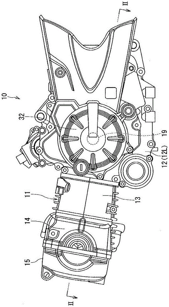
[0064] figure 1 It is a left side view showing the engine unit of the motorcycle to which the first embodiment of the motorcycle generator according to the present invention is applied. figure 1 Among them, the power unit 10 has an air-cooled four-stroke single-cylinder engine 11, and the engine 11 is mainly composed of: a crankcase 12 that rotatably supports and accommodates a crankshaft 19; a cylinder block 13 that is coupled to the end of the crankcase 12; a cylinder head 14 coupled to the cylinder block 13 ; and a head cover 15 coupled to the cylinder head 14 . In addition, the motorcycle generator of the present invention is installed in a power unit of the motorcycle.

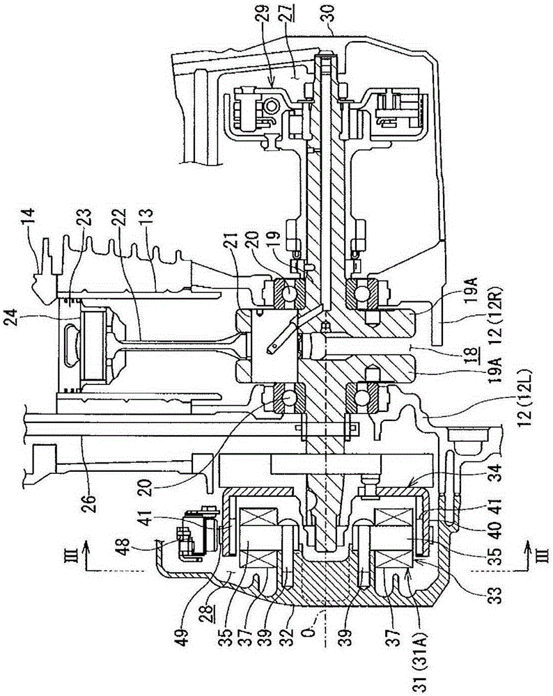
[0065] In this embodiment, the crankcase 12 is divided into two left and right. exist figure 2 In the crankcase 12 , a right crankcase 12R and a left crankcase 12L which are a pair of left and right are mutually coupled to form a crank chamber 18 integrally. In the crank chamber 18 , a crankshaft 1...

no. 2 Embodiment approach

[0088] Next, refer to Figure 12 to Figure 2 0 A second embodiment of the motorcycle generator of the present invention will be described.

[0089] The motorcycle generator according to the second embodiment is installed in the power unit of the motorcycle according to the first embodiment, and it is different from the motorcycle generator shown in the first embodiment. Figure 1 to Figure 3 The structure of the magnetic device 31 is the same, so the same structure is marked with the same symbol to omit or simplify the repeated description.

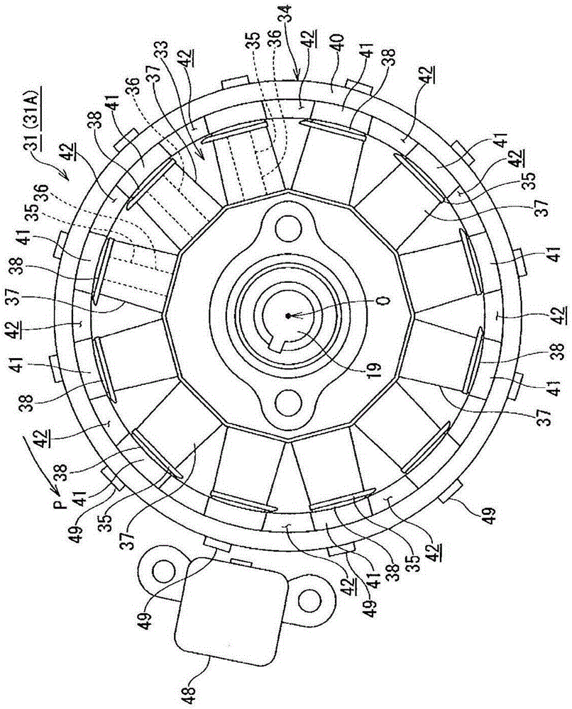
[0090] The motorcycle generator of the second embodiment has a single-phase or three-phase magnetic alternator 31A as a magnetic device. Such as Figure 12 As shown, the magneto generator 31A is configured to include: a stator 33 arranged coaxially with the crankshaft 19 and arranged around the crankshaft 19 ; The rotor 34 is fixed on the left side shaft end of the crankshaft 19, and the rotation direction of the rotor 34 is determined...


PUM

PropertyMeasurementUnit
Thicknessaaaaaaaaaa
Thicknessaaaaaaaaaa
Thicknessaaaaaaaaaa

Abstract

A generator for a motorcycle is disposed within the power unit of the motorcycle and has: a stator configured by winding stator coils around stator teeth, respectively, the stator teeth extending radially from the center; and a rotor configured by arranging magnets on the inner peripheral surface of a rotor yoke and rotating about the center, i.e., around the stator. The generator for a motorcycle is configured in such a manner that: the magnets are arranged in the circumferential direction of the rotor so as to be adjacent to each other with gaps therebetween; the stator teeth are formed by stacking core sheets on each other, the core sheets being thin sheets of steel; the stator teeth each have tip sections extending in the rotational direction of the rotor and in the direction opposite the rotational direction, from the coil-wound section of the stator tooth, the coil-wound section being that around which the stator coil is wound; and when the leading end of a magnet in the rotational direction substantially coincides with the centerline of the coil-wound section, one of the tip sections of each of the stator teeth, said tip section extending in the rotational direction of the rotor, overlaps the preceding magnet adjacent to the leading end of the magnet in the rotational direction.

Description

technical field [0001] The present invention relates to a motorcycle generator capable of reducing electric loss and improving power generation output and power generation efficiency. Background technique [0002] As a generator for motorcycles, it is known that there is a Figure 22 The structure shown uses a magneto generator 100 . This magneto generator 100 has: a stator 103 in which a stator (power generation) coil 102 is wound around a plurality of stator teeth 101; By the action of electromagnetic induction generated by the rotor 106 rotating around the stator 103 by the driving force of the engine, an induced current is induced in the generator coil 102 to generate power. [0003] In magneto 100 , for example, four magnets 105 are provided on the inner peripheral surface of rotor yoke 104 . Such as Figure 23 As shown, in each magnet 105, three magnetic poles constituting a pair of N pole and S pole are magnetized. Therefore, magnetic flux tends to leak to adjacen...

Claims


Application Information

Patent Timeline
IPC IPC(8): H02K21/22H02K1/14
CPCH02K1/14H02K21/22
Inventor 刑部铁也
Owner SUZUKI MOTOR CO LTD
Why Eureka
Try Eureka