Nd-Fe-B powder molding press

A technology of NdFeB powder, which is applied in the field of NdFeB powder molding presses, can solve the problems of impossibility of adopting near-net shape pressing technology, increase of pressing cost, production time, weight and overall size mismatch, and achieve structural Simple and ingenious, the overall size is reduced, and the effect of reducing energy consumption

Active Publication Date: 2016-05-11
宁波钉子博士磁性技术有限公司
View PDF8 Cites 12 Cited by
  • Summary
  • Abstract
  • Description
  • Claims
  • Application Information

AI Technical Summary

Problems solved by technology

[0026] (1) After the first step of pressing, the mechanical properties of the magnet compact are poor, and it cannot be sintered immediately, and cold isostatic pressing equipment is required for the second pressing
[0027] (2) Low degree of automation leads to high labor costs
[0028] (3) The second step of cold isostatic pressing technology not only increases the pressing cost and production time, but also increases the risk of contamination with air, oil and other consumables
[0029] (4) Due to the need for packaging before CIP, it

Method used


Image

  • Nd-Fe-B powder molding press
  • Nd-Fe-B powder molding press
  • Nd-Fe-B powder molding press

Examples


Embodiment 1

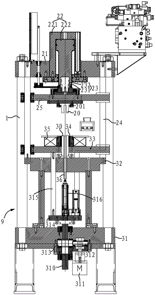
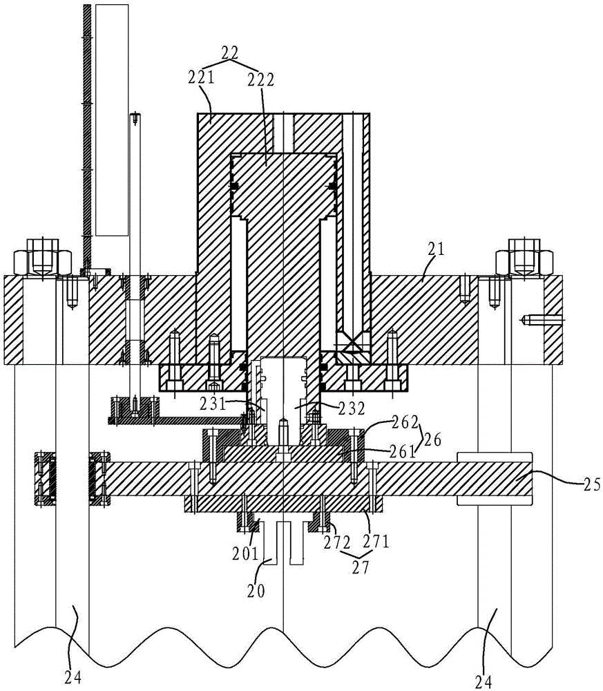
[0113] Such as Figure 1 ~ Figure 3 As shown, the upper punch assembly in this embodiment includes an upper pressing plate 21 , a main hydraulic cylinder 22 , a pressure release piston 232 , an upper punch 20 , a guide column 24 , and an upper guide plate 25 .

[0114] Wherein, the upper pressing plate 21 is fixedly installed on the top of the frame 1 , and the main hydraulic cylinder 22 is embedded and fixed in the center of the upper pressing plate 21 . The main hydraulic cylinder 22 includes a cylinder body 221 and a piston 222 , and the piston 222 can move up and down in the cylinder body 221 of the main hydraulic cylinder 22 driven by hydraulic oil.

[0115] Wherein the lower end of the main hydraulic cylinder 22 piston 222 is provided with an accommodating cavity opening downwards, and this accommodating cavity then forms a release cylinder 231, and the release piston 232 is installed in the release cylinder 231, thereby being compatible with the pressure release cylinde...

Embodiment 2

[0143] Such as Figure 4 As shown, the difference between the present embodiment and the first embodiment is only that the mold 34 , the supporting table 32 , and the lower punch 30 surround and form a lubricating cavity 4 for lubricating the inner wall of the mold 34 . The working principle of the lubricating assembly is the same as that of the first embodiment.

[0144] In addition, in this embodiment, each guide column 24 is connected between the upper pressing plate 21 and the lower pressing plate 31 . The support platform 32 is located above the lower platen 31 , and the mold 34 is installed on the support platform 32 . The lower guide plate 33 is located between the supporting platform 32 and the lower pressing plate 31 . In this embodiment, a magnetically conductive plate 37 is also provided on the support table 32, an upper coil 38 is arranged around the upper punch 20, a lower coil 39 is arranged around the lower punch 30, and the connection between the upper coil 3...


PUM


Abstract

The invention relates to an Nd-Fe-B powder molding press. The Nd-Fe-B powder molding press comprises a rack, an upper punching assembly and a lower punching assembly, wherein the upper punching assembly and the lower punching assembly are arranged on the rack from top to bottom. The upper punching assembly comprises an upper pressing plate, a main hydraulic cylinder, a pressure relief piston and an upper punch, wherein the upper pressing plate is fixedly mounted on the upper portion of the rack; the main hydraulic cylinder comprises a cylinder block mounted on the upper pressing plate and a piston arranged in the cylinder block in an up-down moving mode; the lower end of the piston is provided with a containing cavity with a downward opening; the containing cavity forms a pressure relief cylinder block; the pressure relief piston is arranged in the pressure relief cylinder block in an up-down moving mode, and the pressure relief piston and the pressure relief cylinder block form a pressure relief cylinder; the upper punch is connected to the lower end of the pressure relief piston. According to the Nd-Fe-B powder molding press, the pressure relief cylinder is embedded in a piston of the main hydraulic cylinder; the structure is simple and ingenious; the overall dimensions of the Nd-Fe-B powder molding press are greatly reduced; the matching performance of the weight and the overall dimensions of the press and the dimensions of pressing blanks are improved; energy consumption is effectively reduced on the premise of guaranteeing the production efficiency.

Description

technical field [0001] The invention relates to the technical field of forming presses, in particular to an NdFeB powder forming press. Background technique [0002] Permanent magnets are made of rare earth alloys, mainly Nd 2 Fe 14 B. Sm 2 co 17 and SmCo 5 Made of metal alloy. Permanent magnets have unique high-density magnetic energy. The preparation of permanent magnets requires the use of expensive raw materials and huge production costs. The technology for producing permanent magnets must meet certain requirements in order to obtain the best raw material output and the best magnetic properties. The main production steps of permanent magnets are: melting the alloy; grinding the alloy into a particle powder usually smaller than 10 microns; pressing the particle powder into a magnetic field, and then sintering the compact; obtaining the final desired shape of the magnet through machining, and finally magnetizing the magnet. [0003] Among them, powder compaction is t...

Claims


Application Information

Patent Timeline
IPC IPC(8): B22F3/03H01F1/057
CPCB22F3/003B22F3/004B22F3/03B22F2999/00H01F1/0576B22F3/02B22F2202/05
Inventor 赫尔伯特·纳格尔肖名剑郑阳张龙杨岳辉
Owner 宁波钉子博士磁性技术有限公司
Why Eureka
Try Eureka