Novel brush type seal and production method thereof

A brush type sealing and manufacturing method technology, applied in the direction of preventing leakage, engine components, machines/engines, etc., can solve the problems of low uniformity and precision of wire laying, various specifications of wire laying templates, and unchangeable wire laying angle, etc. Achieve the effect of reducing labor intensity of workers, realizing product standardization, and improving uniformity and precision

Active Publication Date: 2016-05-11
江苏鑫信润科技股份有限公司
View PDF6 Cites 2 Cited by
  • Summary
  • Abstract
  • Description
  • Claims
  • Application Information

AI Technical Summary

Problems solved by technology

[0003] Because the manufacture of the traditional brush seal needs to process the front guard plate, rear guard plate and brush wire bundle of the corresponding arc section in advance according to the different arcs of the steam seal, and then clamp according to the actual needs and adapt after welding, so There are several problems: (1) mass production cannot be carried out, and effective inventory cannot be carried out at the same time; (2) the manufacturing process requires the use of wire arrangement templates, and the need to manually fill the tow into the template, the uniformity and precision of the wire arrangement are relatively low. Low, and the production efficiency is not high; (3) The angle of wire arrangement cannot be changed, generally 45°, if you want to change the angle of wire arrangement, you need to replace the wire arrangement template, and there are many specifications of the wire arrangement template; (4) The arrangement direction of the brush seal is affected The influence of the rotor rotating clockwise and counterclockwise, the scrap rate is high

Method used


Image

  • Novel brush type seal and production method thereof
  • Novel brush type seal and production method thereof
  • Novel brush type seal and production method thereof

Examples


Embodiment Construction

[0039] The present invention will be further described below in conjunction with the accompanying drawings. The following examples are only used to illustrate the technical solution of the present invention more clearly, but not to limit the protection scope of the present invention.

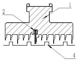
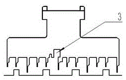
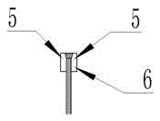
[0040] A new type of brush seal, the structure is as follows figure 1 As shown, it includes a steam seal block 1 and a brush seal 2. The steam seal block 1 is provided with a plurality of high teeth and low teeth for sealing. The steam seal block 1 is also provided with a brush seal groove 3. The brush seal groove 3 is set in The steam seal block 1 is close to the high teeth, and is located on the intake side of the corresponding high teeth; the brush seal 2 is fixed in the brush seal groove 3, and the structure of the brush seal 2 is as follows: image 3 As shown, it includes two brush wire guards 5 and the brush wire 6 arranged between the two brush wire guards 5; the two brush wire guards 5 ...


PUM


Abstract

The invention discloses a novel brush type seal which comprises a steam seal block and a brush seal, wherein a brush seal groove is formed in the steam seal block; the brush seal is fixed in the brush seal groove and comprises two wire brush protecting plates and brush wires arranged between the two wire brush protecting plates; the two wire brush protecting plates are identical in height and are separately lower than the brush wires; a separation blade for preventing the brush wires from being inclined is arranged below the air outlet side of the brush seal groove; and the separation board and the steam seal block form an integrated structure. According to the novel brush type seal disclosed by the invention, in production of the novel brush type seal, a direct type brush seal is first produced, and then is subjected to rolling-bending forming, so that the defects that an existing process is troublesome in production, poor in generality and the like are overcome; the novel brush type seal can be produced on batch, and is effective in inventory and good in generality; the influence of clockwise and counter-clockwise rotation of a rotor on the arraying direction of the brush seal is eliminated, the rejection rate is reduced and an original wire arraying template is discarded; and by adopting an automatic wire winding process, labor intensity is reduced, the uniformity and the precision of arrayed wires are improved, and the production efficiency is greatly improved.

Description

technical field [0001] The invention relates to a novel brush seal and a manufacturing method thereof, belonging to the technical field of sealing equipment. Background technique [0002] The brush seal is a high-efficiency damping seal developed in recent years. Its leakage is 1 / 5-1 / 10 of that of the comb labyrinth seal. It improves the efficiency of the unit and improves the stability of the rotor, and has been applied to turbomachinery such as aero-engines, industrial gas turbines and steam turbines. The main structure of the brush seal is to install a circle of brush seals on the basis of the original steam seal, and replace the original high teeth with the brush seals. The height is higher than the original high teeth, because the clearance of the steam seal is reduced, thereby reducing Air leakage, the brush wires in the sealing part are arranged in a circle of high-temperature-resistant alloy wires along the direction of rotor rotation, which can withstand high tempe...

Claims


Application Information

Patent Timeline
Patent Type & Authority Applications(China)
IPC IPC(8): F01D11/00B23P15/00
CPCB23P15/00F01D11/00
Inventor 左飞申先念李国民
Owner 江苏鑫信润科技股份有限公司
Why Eureka
Try Eureka