Method and system for waste recycling and treatment
A technology for waste recycling and waste cinder, which is applied in the field of boiler combustion, can solve the problems of energy reuse of waste cinder caused by flue gas pollution, etc., and achieves the effects of simple method, convenient operation and avoiding environmental pollution.
- Summary
- Abstract
- Description
- Claims
- Application Information
AI Technical Summary
Problems solved by technology
Method used
Image

Examples
Embodiment 1
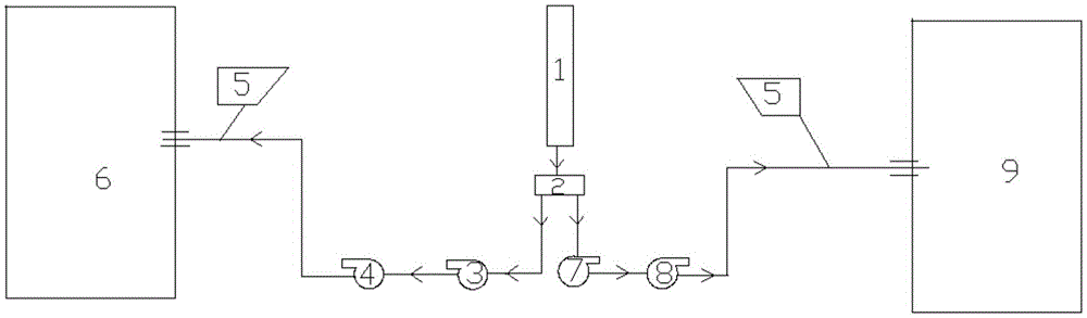
[0043] Such as figure 1As shown in the figure, a system for waste recovery and treatment, the oil fume flue 1 of the heat conduction oil furnace is connected to the induced draft fan I3 and the induced draft fan II7 of the 1# coal-fired boiler 6 through the electric dust removal equipment and the bag dust removal equipment 2, and the induced draft fan I3 is connected to Primary fan I4 of 1# coal-fired boiler 6. The induced draft fan II7 is connected to the primary fan II8 of the 2# coal-fired boiler 9.
[0044] Both the 1# coal-fired boiler and the 2# coal-fired boiler are connected to the pulverized coal bin 5. Primary air is used to convey and dry coal powder, and provide oxygen for volatile combustion in coal powder.
[0045] The method of use is as follows: the oil fume generated by the heat conduction oil furnace enters the oil fume flue 1 through the flue gas outlet to meet, and then goes through the electrostatic precipitator and bag dust removal equipment 2 for dust ...
Embodiment 2
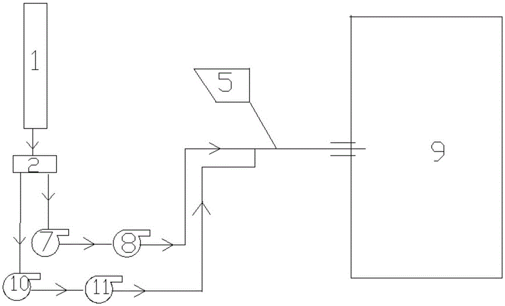
[0048] As a specific embodiment, such as figure 2 As shown, a system for waste recovery and treatment, 2# coal-fired boiler has two primary fans, and the oil fume flue 1 of the heat-conducting oil furnace is connected to the induced draft fan Ⅱ7 of 2# coal-fired boiler through electric dust removal equipment and bag dust removal equipment 2 And the induced draft fan III10, the induced draft fan II7 is connected to the primary fan II8 of the 2# boiler, and the induced draft fan III11 is connected to the primary fan III11 of the 2# coal-fired boiler.
[0049] The oil fume flue 1 in the present invention is not limited to connecting two induced draft fans of one boiler, but can also connect multiple induced draft fans of one boiler.
Embodiment 3
[0051] A method for recovery and treatment of waste (oil fume), the applicant adopts the system in Example 1 to recycle the oil fume produced by the heat conduction oil furnace into the 1# coal-fired steam boiler and 2# coal-fired steam boiler for steam supply, and control The flow ratio of air to oil fume is 400:1m 3 / h.
[0052] See Table 1 below for the relevant parameters before and after recovery of the oil fume generated by the heat conduction oil furnace.
[0053] Table 1 Comparison table before and after oil furnace flue gas recovery
[0054] Process parameters
Before 1# boiler is put into use
After 1# boiler is put into use
Before 2# boiler is put into use
After the 2# boiler is put into use
Load T / H
56
56
43
43
Bed temperature ℃
983-986
992-990
985-980
988-990
Furnace differential pressure pa
110
142
142
117
Furnace outlet negative pressure pa
-114
-125Pa
...
PUM
 Abstract
Description
Claims
Application Information
 - R&D
- Intellectual Property
- Life Sciences
- Materials
- Tech Scout
- Unparalleled Data Quality
- Higher Quality Content
- 60% Fewer Hallucinations
Browse by: Latest US Patents, China's latest patents, Technical Efficacy Thesaurus, Application Domain, Technology Topic, Popular Technical Reports.
© 2025 PatSnap. All rights reserved.Legal|Privacy policy|Modern Slavery Act Transparency Statement|Sitemap|About US| Contact US: help@patsnap.com